
Electric landing gear actuation systems on modern aircraft ¡ª from business jets and regional turboprops to large commercial transports experimenting with electrification ¡ª use a planetary gearbox to convert electric motor output into the large mechanical force required to retract and extend the landing gear against aerodynamic loads, gravity, and gear door spring forces. The system must complete a full retraction or extension cycle in 5 to 15 seconds, hold the gear rigidly in the retracted or extended position without continuous power consumption, and be capable of gravity extension without any power if the primary actuation system fails. The planetary gearbox is the element that reconciles the motor high speed with the actuator need for very high force at very slow speed.
Landing Gear Actuation Requirements
The force required to retract a main landing gear depends on the gear weight, the aerodynamic loads during retraction, and the spring forces from gear door actuators. For a business jet, the total retraction force on one main gear may be 15 to 30 kN applied over 0.4 to 0.8 m of actuator travel, at a rate of 0.05 to 0.10 m/s during retraction. From a 400 W electric motor at 10 000 rpm through a ballscrew with 10 mm lead, the required motor torque is approximately 0.9 N¡¤m ¡ª within a small servo motor capability when an appropriate planetary ratio is selected.
Self-Locking and Gear-Up Position Holding
When the landing gear is retracted and locked, the actuator must hold the gear in the wheel well against aerodynamic suction loads without continuous motor current. Three holding methods are used: a mechanical uplatch that locks the gear structure in the retracted position, a self-locking screw at low lead angle which is irreversible without powered backdrive, or a motor brake that is spring-applied when the motor is de-energised. Most aircraft use an uplatch as the primary holding device and the actuator as the force source only during retraction and extension.
| Holding Method | Mechanism | Reliability | Weight | Complexity |
|---|---|---|---|---|
| Mechanical uplatch | Latch hooks gear structure | Highest passive | Low | Requires release mechanism |
| Self-locking screw | Lead screw below friction angle | High passive | Low | Limited speed lower efficiency |
| Motor brake | Spring-applied electromagnetic release | High electrical | Moderate | Requires power to release |
| Hydraulic lock | Check valve traps fluid | Very high | Moderate | Requires fluid circuit |
| Continuous power | Motor holds continuously | Low power required | Very low | Not used in practice |
Uplatch is standard on most fixed-wing aircraft; motor brake is common on electric actuation systems.
Backlash and Position Accuracy Requirements
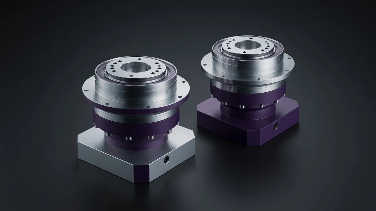
Landing gear actuation systems do not require the sub-arc-minute positioning accuracy of CNC or robot joints ¡ª the primary requirement is reliable full extension and full retraction within the timing budget, and positive lock engagement when fully extended. Backlash in the planetary gearbox is therefore less critical than in servo applications; 5 to 10 arc-minutes is acceptable. The more critical property is torsional stiffness ¡ª the actuator must resist the aerodynamic loads that try to push the gear out of the wheel well without excessive compliance. The AB115 high-precision planetary series provides the torsional stiffness needed to resist actuator compliance in landing gear applications, and the AD110 right-angle planetary series serves installations where the actuator must fit in a constrained space requiring a perpendicular output shaft relative to the motor axis.
Emergency Extension and Gravity Drop
All aircraft landing gear systems must provide a means of extending the gear in an emergency if the primary powered actuation system fails. For hydraulic systems, this is a manual valve release allowing the gear to fall under gravity. For electric actuator systems, the emergency extension may be by manual hand crank that back-drives the planetary gearbox and actuator to release the uplatch, or by a dedicated emergency battery-powered motor. The planetary gearbox must be back-driveable by the manual crank at the force a pilot can apply ¡ª typically 100 to 200 N at the crank handle ¡ª which sets an upper limit on the gearbox ratio and the actuator lead screw efficiency that the designer must respect to ensure gravity extension remains possible. For comparable precision actuator drives in demanding applications, the VRV040 precision worm gearbox illustrates the alternative approach where self-locking is used as the position-holding mechanism.
Frequently Asked Questions
Speak with a Planetary Drive Specialist
Share your torque requirement, ratio, and application environment ¡ª our team at Condell Park NSW returns a sized recommendation and stock check within one business day. No obligation.