
Hydroelectric turbines connected to generators through a planetary gearbox represent one of the most demanding long-life drive applications in any industry ¡ª the Snowy Mountains Scheme, the Gordon Power Station in Tasmania, and the small run-of-river hydro stations scattered through Victoria’s high country all require their drive components to operate for 30 to 50 years between major overhauls. The planetary gearbox in a geared hydro installation reduces the low rotational speed of the turbine ¡ª Kaplan and Francis turbines typically run at 50 to 300 rpm ¡ª to the synchronous speed of the generator, typically 375, 500, or 750 rpm for 50 Hz systems.
Turbine Types and Speed Requirements
Not all hydroelectric turbines use a gearbox ¡ª large high-head Francis and Pelton turbines run fast enough to drive generators directly, and large Kaplan turbines use slow-speed generators specifically designed for the turbine speed. Geared arrangements are most common in small and micro-hydro installations below 10 MW where the turbine speed is in the range of 50 to 200 rpm, the generator is a standard synchronous generator designed for 375 or 750 rpm, and the planetary gearbox bridges the gap. The ratio required is modest ¡ª typically 2:1 to 6:1 ¡ª achievable in a single compact planetary stage with exceptional efficiency.
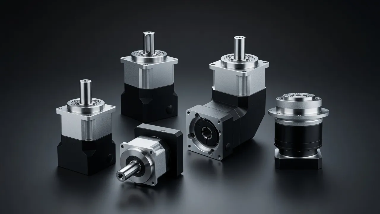
| Turbine Type | Head Range | Runner Speed | Generator Speed | Required Ratio | Power Range |
|---|---|---|---|---|---|
| Micro Pelton | 50¨C500 m | 600¨C1 500 rpm | 1 000¨C1 500 rpm | 1.5:1¨C2.5:1 | 10¨C500 kW |
| Small Francis | 20¨C150 m | 150¨C500 rpm | 375¨C750 rpm | 1.5:1¨C3:1 | 100 kW¨C5 MW |
| Small Kaplan | 5¨C20 m | 80¨C200 rpm | 375¨C500 rpm | 2:1¨C6:1 | 100 kW¨C5 MW |
| Crossflow Banki-Michell | 2¨C40 m | 100¨C300 rpm | 375¨C750 rpm | 1.5:1¨C4:1 | 10¨C500 kW |
| Run-of-river Archimedes | 1¨C5 m | 20¨C60 rpm | 375 rpm | 6:1¨C20:1 | 10¨C500 kW |
Generator synchronous speeds for 50 Hz: 3 000 two-pole, 1 500 four-pole, 750 eight-pole, 500 twelve-pole, 375 sixteen-pole rpm.
Efficiency Requirements for 30-Year Payback
A small hydro installation with a 500 kW turbine operating at 70% capacity factor generates 3 066 MWh per year. At the current Australian wholesale electricity price, each percentage point of gearbox efficiency represents approximately $2 000 to $5 000 in annual revenue. Over a 30-year project life, a gearbox with 97.5% efficiency versus 96.5% efficiency generates $60 000 to $150 000 more revenue from the same water resource. This is a compelling argument for specifying the most efficient planetary gearbox available, even at higher initial cost. The EPG one-stage precision planetary series provides the ground helical gear precision and hydrodynamic oil film design needed for hydro drive applications, delivering single-stage efficiency above 98% across the operating load range. For hydro installations requiring two-stage reduction, the EPG two-stage precision planetary achieves compound efficiency of 96.5% to 97.5% in a compact housing.
Long-Life Bearing Selection and Lubrication
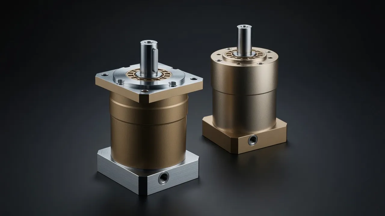
A hydroelectric gearbox operating at 70% capacity factor runs 6 132 hours per year. Over 30 years, the input shaft bearing completes approximately 184 000 hours of operation. Standard deep-groove ball bearings rated at 20 000 to 50 000 hours L10 life are inadequate for this application ¡ª they would require replacement every 3 to 8 years, requiring turbine shutdown and machine room access. Rolling element bearings with L10 life calculated at 100 000 hours under the actual hydro load spectrum, or hydrodynamic sleeve bearings, are the appropriate choice for bearings that the designer intends to last the turbine service life.
Vibration and Noise in Sensitive Environments
Small hydro installations near residential areas ¡ª run-of-river stations on NSW alpine streams, micro-hydro on rural properties ¡ª must meet environmental noise limits. The planetary gearbox is typically the dominant noise source in the machine room, and its noise radiates through the machine room structure and housing. Helical gears generate less noise than spur gears at the same ratio because the helix angle distributes the tooth contact progressively rather than simultaneously across the full face width, reducing the transmission error at each mesh cycle. A helix angle of 20 to 30 degrees typically reduces gear mesh noise by 5 to 10 dB compared with equivalent spur gears. For comparable low-noise precision drive applications, the VRV040 precision worm gearbox illustrates the noise reduction techniques applied in precision industrial drives operating in noise-sensitive environments.
Frequently Asked Questions
Speak with a Planetary Drive Specialist
Share your torque requirement, ratio, and application environment ¡ª our team at Condell Park NSW returns a sized recommendation and stock check within one business day. No obligation.