Description
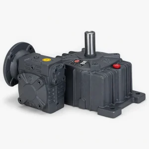
EA Series Double Worm Gear Reducer — Ultra-High Ratios
When a single worm stage cannot deliver the reduction ratio your process demands, the EA Series steps in with two cascaded worm gear pairs housed in a bolted dual-casing assembly. Total ratios from 200:1 to 900:1 produce extremely low output speeds — as slow as 1.7 r/min from a standard 1,500 r/min motor — with output torques reaching up to 9,066 N·m on the largest frame combination. This makes the EA a purpose-built solution for crane travel drives, kiln rotators, heavy gate actuators, and any application where a very slow, very powerful, and inherently self-locking gear reducer is required. Nine frame combinations (WP40–70 through WP155–250) cover inputs from 0.12 kW fractional motors up to 5.5 kW industrial drives, and the foot-mounted housing bolts to a standard machine base without special adapters.
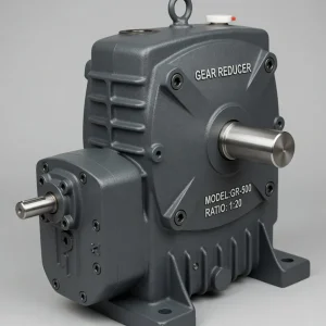
How Double-Stage Reduction Works
Inside the EA, the first-stage worm shaft meshes with a first-stage bronze worm wheel, reducing the motor speed by a factor of 10:1 to 30:1. The first-stage worm wheel shares a common shaft with the second-stage worm, which then meshes with a second bronze worm wheel at an additional 10:1 to 30:1. The total ratio is the product of the two individual ratios: a 15:1 first stage times a 20:1 second stage produces a total 300:1 output ratio. Because both worm sets operate at moderate individual ratios, each stage sits within its peak efficiency band, and the combined self-locking threshold is far lower than what a single stage would need — meaning the EA locks under virtually any load at any of its standard ratios.
Performance Specifications
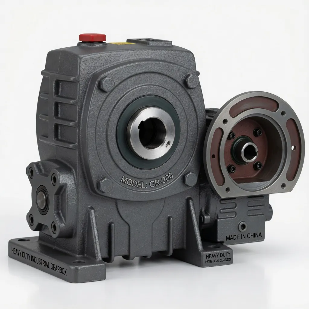
The table below shows key data for the EA Series at 1,500 r/min input. Frame combinations pair a smaller first-stage housing with a larger second-stage housing. All units use the same WP-platform worm gear reducer castings, bearings, and worm-wheel alloy found across the single-stage range, so spare parts are interchangeable per frame size. For full dimensional data, contact us with your required frame combination and ratio.
| Frame Combination | Input Motor (kW) | Ratio Range | Output Torque at 300:1 (N·m) | Max Output Torque (N·m) |
|---|---|---|---|---|
| WP40–70 | 0.12 | 200:1 – 900:1 | 88 | 177 |
| WP60–100 | 0.37 | 200:1 – 900:1 | 276 | 561 |
| WP80–135 | 1.5 | 200:1 – 900:1 | 880 | 1,811 |
| WP100–155 | 1.5 | 200:1 – 900:1 | — | — |
| WP120–175 | 2.2 – 3 | 200:1 – 900:1 | 2,340 | 4,463 |
| WP135–200 | 3 – 4 | 200:1 – 900:1 | — | — |
| WP155–250 | 5.5 | 200:1 – 900:1 | 4,087 | 9,066 |
Industry Applications
Crane and Hoist Travel Drives
Overhead bridge cranes and gantry cranes from Demag, Konecranes, and SWF often use double-stage worm reducers on the travel-wheel drive. A WP120–175 EA at 400:1 turns a 1,500 r/min motor into a 3.75 r/min output, producing the slow, controlled bridge movement that heavy-lift operations demand. The dual self-locking stages hold the bridge in position the moment the motor stops, without relying on the motor brake alone — an important safety redundancy.
Rotary Kilns and Dryers
Cement kilns, lime kilns, and rotary dryers rotate at 1–5 r/min under enormous torque loads. The WP155–250 EA generates over 9,000 N·m of continuous output torque — enough to turn a loaded kiln shell through a pinion gear. The industrial gearbox construction of the EA handles the thermal cycling and vibration inherent in kiln-drive environments, and the foot-mounted housing bolts to the concrete drive pedestal alongside the kiln bearing blocks.
Flood Gates and Dam Sluices
Municipal and irrigation dam gates need very slow, very strong drives that hold position without power. The EA’s inherent self-locking at every ratio eliminates the need for a separate gate-locking mechanism. Frame combinations WP80–135 and WP100–155 are commonly specified for gate-leaf widths up to 4 metres, paired with a screw-jack or rack-and-pinion output stage.
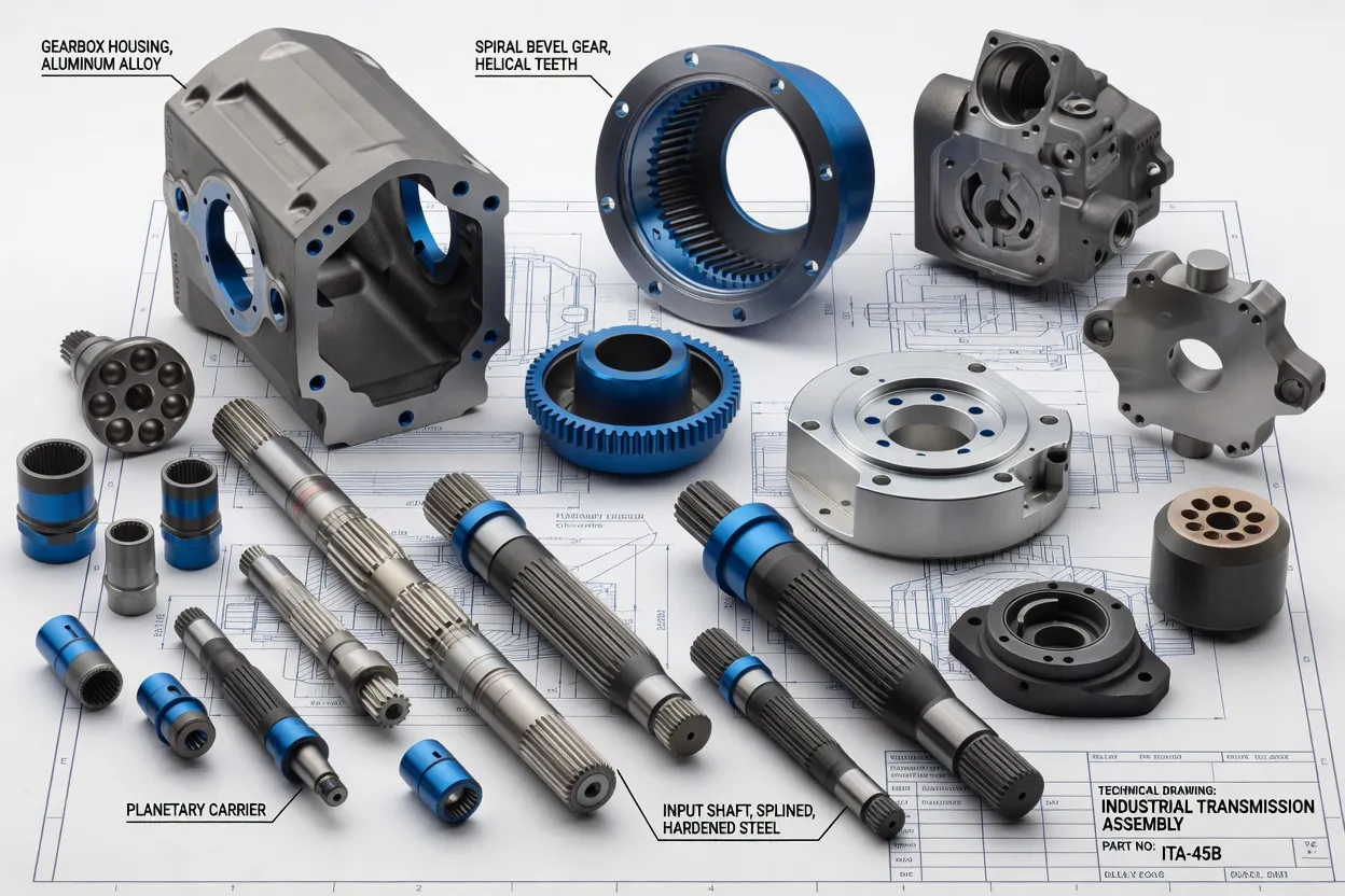
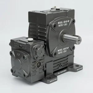
Dual worm-wheel assemblies and hardened worm shafts
Thermal Management and Lubrication
Double-stage worm reducers generate more heat than single-stage units because two sliding-contact gear meshes operate in series. For continuous duty above six hours, we recommend a synthetic ISO VG 220 gear oil (such as Mobil SHC 630 or Shell Omala S4 GX 220) to lower operating temperature by 10–20 °C compared with mineral oil. Ensure adequate airflow around both housings — avoid enclosing the EA in an un-ventilated cabinet. The first oil change is at 100 hours; subsequent changes follow a 2,000-hour or annual cycle (shorter than the single-stage 2,500-hour interval) because thermal stress degrades the lubricant faster. Monitor the housing surface temperature during commissioning; a stabilised reading below 95 °C indicates healthy operation.
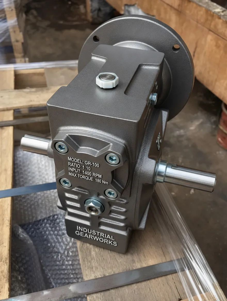
Double-stage reducer assembly and load-testing area
Sourcing from Ever-Power Australia
Ever-Power Transmission Australia Pty Ltd supplies the EA Series and the motor-flange EDA variant from our Condell Park, NSW warehouse. We carry popular frame combinations in stock and can fulfil custom-ratio orders within 3–4 weeks from our manufacturing base. For applications where helical-gear pre-staging would boost system efficiency, consider pairing the EA with our KM helical-hypoid gearboxes line. Reach out via contact us, call +61 2 9708 3322, or email [email protected] for sizing assistance and quotations.