Description
FO Series — Vertical Flange-Output Double Worm Gear Reducer
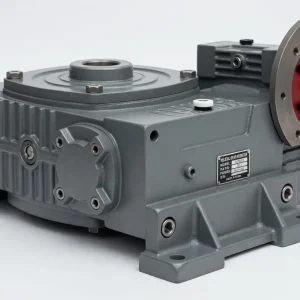
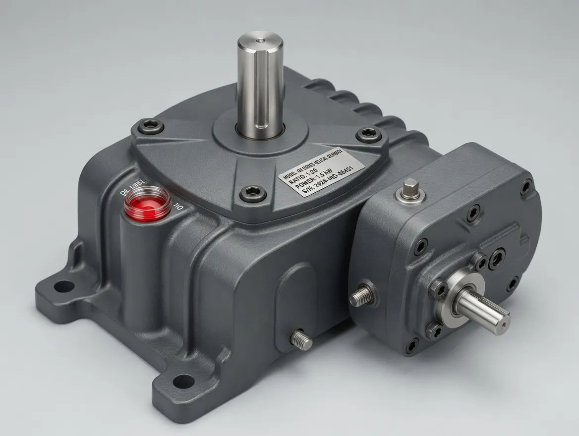
The FO Series mates a double-stage worm gear train with a vertical-upward flange output, allowing the reducer to bolt directly onto machines whose driven shaft points straight up — gate-actuator pedestals, vertical pump brackets, lift-column housings, and solar-tracker pivot mounts. The flange-to-machine connection eliminates the coupling and separate bearing support that a foot-mounted reducer with a solid output shaft would require, producing a shorter, stiffer, and lower-maintenance drivetrain. Five frame combinations from WP40–70 through WP155–250 cover ratios of 200:1 to 900:1 and output torques up to 6,050 N·m. Dual self-locking worm stages provide passive load-holding at every ratio, making this a dependable worm gear reducer for safety-critical vertical drives.
Targeted Applications
Gate-Actuator Pedestals
Penstock and sluice-gate actuators typically bolt to a pedestal mounted on the dam deck, with the gate stem descending vertically through the pedestal centre. The FO’s upward-facing flange bolts directly to the pedestal top plate, and the output shaft connects to the gate-stem coupling inside the pedestal. This layout provides a clean, rigid interface that resists the bending moments generated by water pressure on the gate leaf. The dual self-locking worm gearbox characteristic holds the gate at any lift position without a mechanical gate lock.
Solar-Tracker Pivot Drives
Single-axis and dual-axis solar trackers rotate photovoltaic arrays to follow the sun across the sky. An FO at 400:1 or 600:1 turns a small motor into the slow, precise rotation the tracker needs, and the flange bolts directly to the tracker pivot bearing housing. The inherent self-locking means the array holds its angle in wind gusts without an auxiliary brake, and the right angle worm gearbox geometry keeps the motor parallel to the ground while the output shaft points upward into the tracker hub.
Theatre and Stage Lifts
Orchestra-pit lifts, scenery elevators, and revolving stages need silent, position-holding drives. The FO’s worm mesh produces significantly less noise than helical or planetary alternatives, and the dual self-locking stages hold the platform at any height without relying on a brake that could release during a power failure. The flange output bolts directly to the lift-column drive housing, creating a compact assembly that fits within the pit structure.
Performance Data
Values below apply at 1,500 r/min input under continuous duty. The FO uses the same dual WP-platform castings and gear geometry as the full double-stage speed reducer gearbox range. Output flange dimensions match IEC/GB standards per frame. contact us for full dimensional drawings.
| Frame Combo | Motor (kW) | Ratios | Torque at 300:1 (N·m) | Peak Torque (N·m) |
|---|---|---|---|---|
| WP40–70 | 0.12 – 0.48 | 200:1 – 900:1 | 88 | 250 |
| WP60–100 | 0.37 – 0.95 | 200:1 – 900:1 | 276 | 500 |
| WP80–135 | 1.5 – 2.5 | 200:1 – 900:1 | 880 | 1,400 |
| WP120–175 | 2.2 – 5.09 | 200:1 – 900:1 | 2,340 | 3,050 |
| WP155–250 | 5.5 – 11.71 | 200:1 – 900:1 | 4,087 | 6,050 |
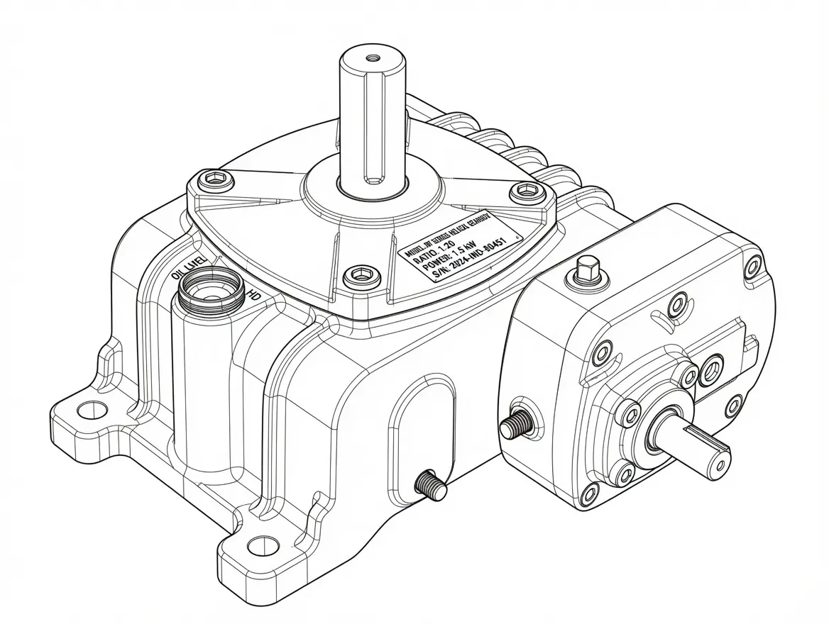
Flange-output face and foot-mounted input layout
Build Quality and Materials
The FO housing is a pair of grey cast-iron casings bolted together with precision dowel pins. The second-stage casing is machined with a vertical output bore and a square flange face ground to 0.05 mm flatness. Internally, both stages use case-hardened 20CrMnTi worm shafts, centrifugally cast ZCuSn10Pb1 tin-bronze worm wheels, tapered roller bearings, and double-lipped NBR oil seals. The first-stage input is a horizontal solid shaft with keyway, accepting a coupling, pulley, or sprocket. All internal components are interchangeable with the EA, EDA, FA, and EO models per frame size.
Components and Spare Parts
Every major component inside this reducer is available as an individual spare part, so a worn gear set or leaking seal never means replacing the entire unit. Our spare-parts inventory covers the full WP-platform range and ships from our Condell Park, NSW warehouse. Every internal component — worm shafts, bronze wheels, bearings, seal kits — is shared with the EA, FA, EDA, and EO models, so one spare-parts inventory covers the entire double-stage range.
Worm Shaft
Case-hardened 20CrMnTi alloy steel, thread-ground to Ra 0.8 μm finish
Worm Wheel
Centrifugally cast ZCuSn10Pb1 tin-bronze, hobbed full-depth involute profile
Bearings
Tapered roller bearings handling combined radial and axial loads on both shafts
Seal & Gasket Kit
Double-lipped NBR oil seals, housing gaskets, breather plugs, and O-rings
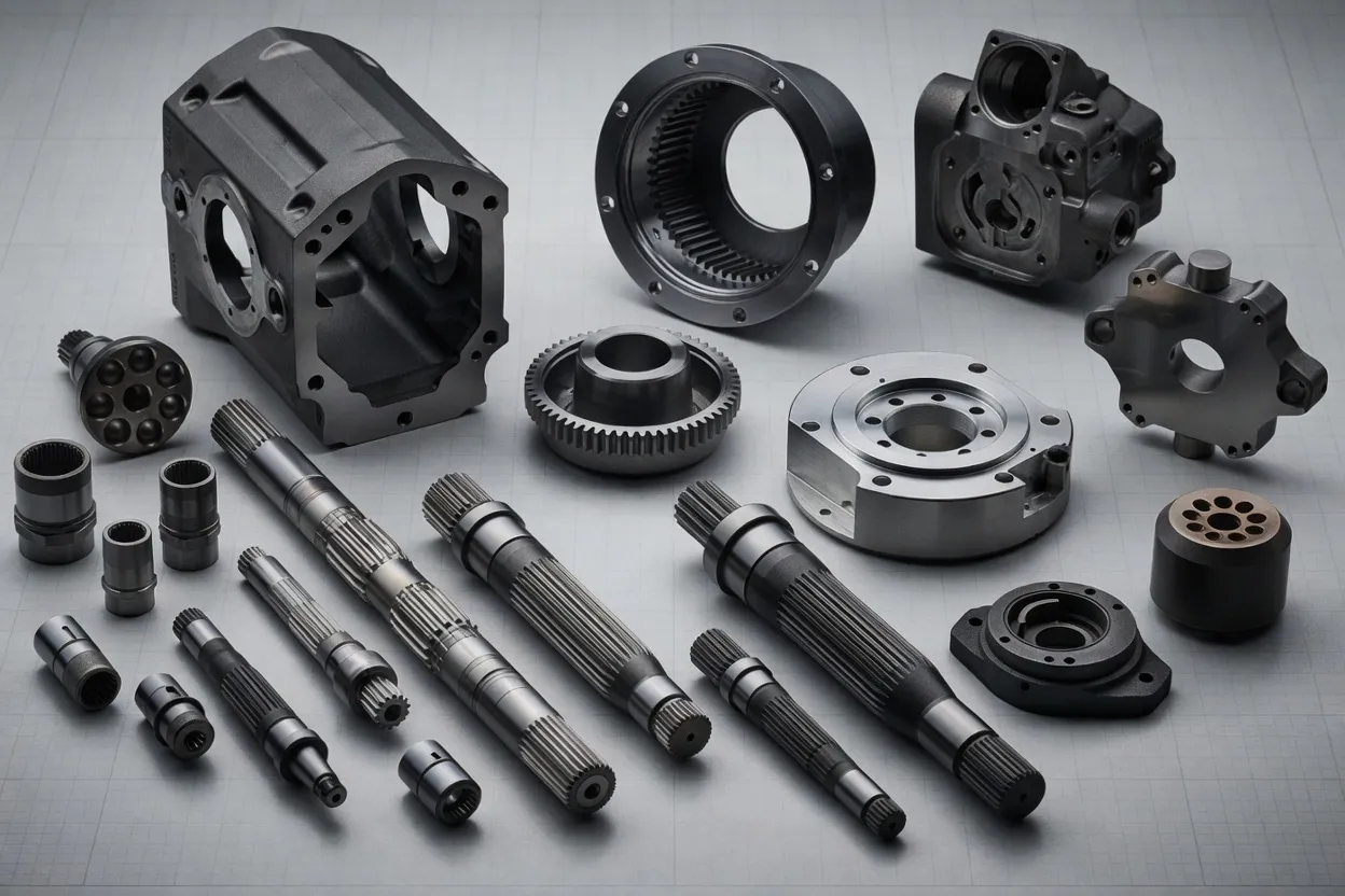
Individual components available for order: worm shaft, bronze wheel, bearings, and seal kits
Lubrication and Thermal Notes
With the output flange facing upward, the second-stage oil fill must fully cover the worm-wheel teeth. Use ISO VG 220–320 EP mineral gear oil for intermittent duty or synthetic ISO VG 220 (Mobil SHC 630, Shell Omala S4 GX 220) for continuous runs above six hours. Oil changes: first at 100 hours, then every 2,000 hours or annually. Keep the breather plug clear and inspect both magnetic drain plugs at each service. Housing surface temperature should stabilise below 95 °C during commissioning.
Customer Reviews
The FO flange output bolted straight onto our existing gate-drive pedestal. Self-locking at 600:1 holds the gate leaf at any intermediate position without a separate gate lock. Very impressed with the build quality.
Ben Marshall
Hydraulics Engineer, Dam Operator
We use the WP80–135 FO on our orchestra-pit lift. Dead silent during performances and the self-locking holds the platform rock-solid at every level. The flange mount made integration with our lift column very clean.
Sophie Grant
Facilities Manager, Performing Arts Centre
Installed three FO units on solar-tracker pivot drives at a regional solar farm. The flange interface reduced installation time compared with foot-mounted alternatives. Running smoothly after two summers.
Daniel Okafor
Project Manager, Renewable Energy
Ever-Power Australia
Our Condell Park, NSW warehouse stocks popular FO frame combinations alongside the full WP double-stage range. Every unit ships factory-tested with ISO 9001 documentation and a complete mounting hardware pack. We also supply SRV086 worm gearbox for forklifts for electric pallet-jack and forklift steering drives. Call +61 2 9708 3322 or email [email protected] for a quotation.
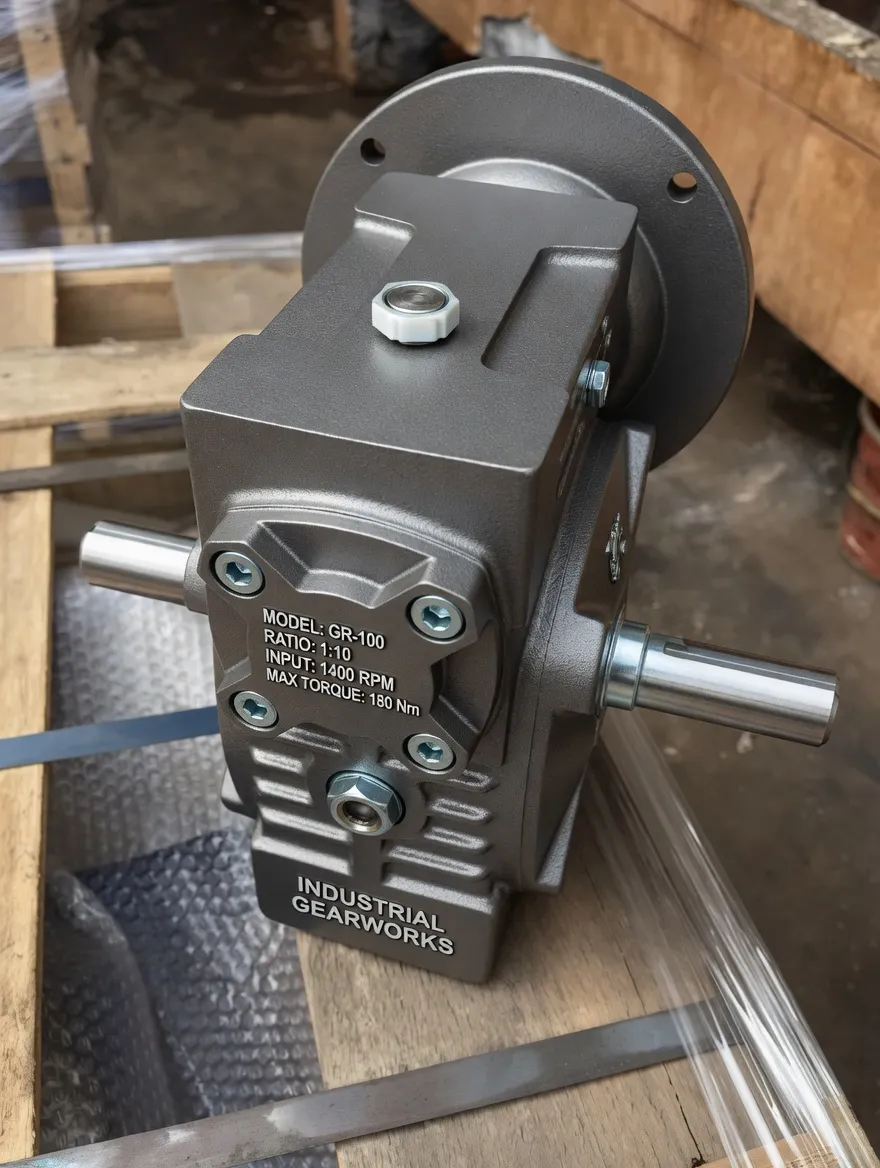
Load testing and final inspection