
A CNC machine axis drive converts servo motor rotation into precise linear or rotational movement of the machine table, saddle, or spindle head. The planetary gearbox between the servo motor and the ball screw (or rack-and-pinion) is the element that defines the positioning resolution, the dynamic stiffness under cutting forces, and the maximum achievable acceleration and deceleration rate. Choosing the wrong ratio, the wrong backlash specification, or the wrong torsional stiffness class can halve the machine’s positioning performance regardless of how sophisticated the servo controller and encoder are.
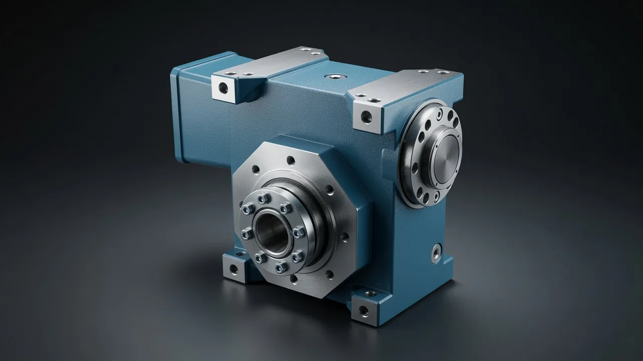
Axis Drive Architecture: Ball Screw vs Rack-and-Pinion
Ball Screw Axis Drives
A ball screw axis drive uses the planetary gearbox output shaft to drive the screw through a coupling, converting rotary motion to linear motion through the screw pitch. At a 20 mm pitch screw driven at 48 rpm (1 440 rpm motor through 1:30 gearbox), table speed is 20 × 48 = 960 mm/min. Positioning resolution at the table depends on the encoder resolution at the motor multiplied by the total mechanical ratio: a 2 500 ppr encoder through 1:30 gearbox and 20 mm pitch screw gives a resolution of 20 ÷ (2 500 × 30) = 0.00027 mm per encoder count — sub-micrometre resolution from modest hardware.
Rack-and-Pinion Axis Drives
Rack-and-pinion axes drive large tables and gantries where ball screw length would be impractical. The planetary gearbox output shaft drives the pinion directly, rolling along the fixed rack. At a 25 mm module pinion (78.5 mm pitch circumference), 48 rpm pinion speed gives 78.5 × 48 ÷ 1000 = 3.77 m/min table speed — suitable for large format routers, plasma cutters, and gantry machining centres. Rack-and-pinion systems are less precise than ball screws because accumulated rack pitch error cannot be fully compensated by software alone, but they enable table travel lengths of 20+ metres that ball screws cannot achieve.
| Axis Length | Preferred Drive | Maximum Speed | Typical Ratio | Backlash Requirement |
|---|---|---|---|---|
| Up to 1 000 mm | Ball screw | 15 m/min | 1:5–1:20 | ≤1 arc-min |
| 1 000–3 000 mm | Ball screw or rack | 25 m/min | 1:5–1:10 | ≤2 arc-min |
| 3 000–8 000 mm | Rack and pinion | 40 m/min | 1:5–1:10 | ≤3 arc-min |
| Over 8 000 mm | Rack and pinion | 60+ m/min | 1:3–1:5 | ≤5 arc-min |
| Rotary axis | Direct or gear | 100–500°/min | 1:10–1:100 | ≤1 arc-min |
Backlash budget shared between gearbox, coupling, and screw/rack. Gearbox should not exceed 50% of total budget.
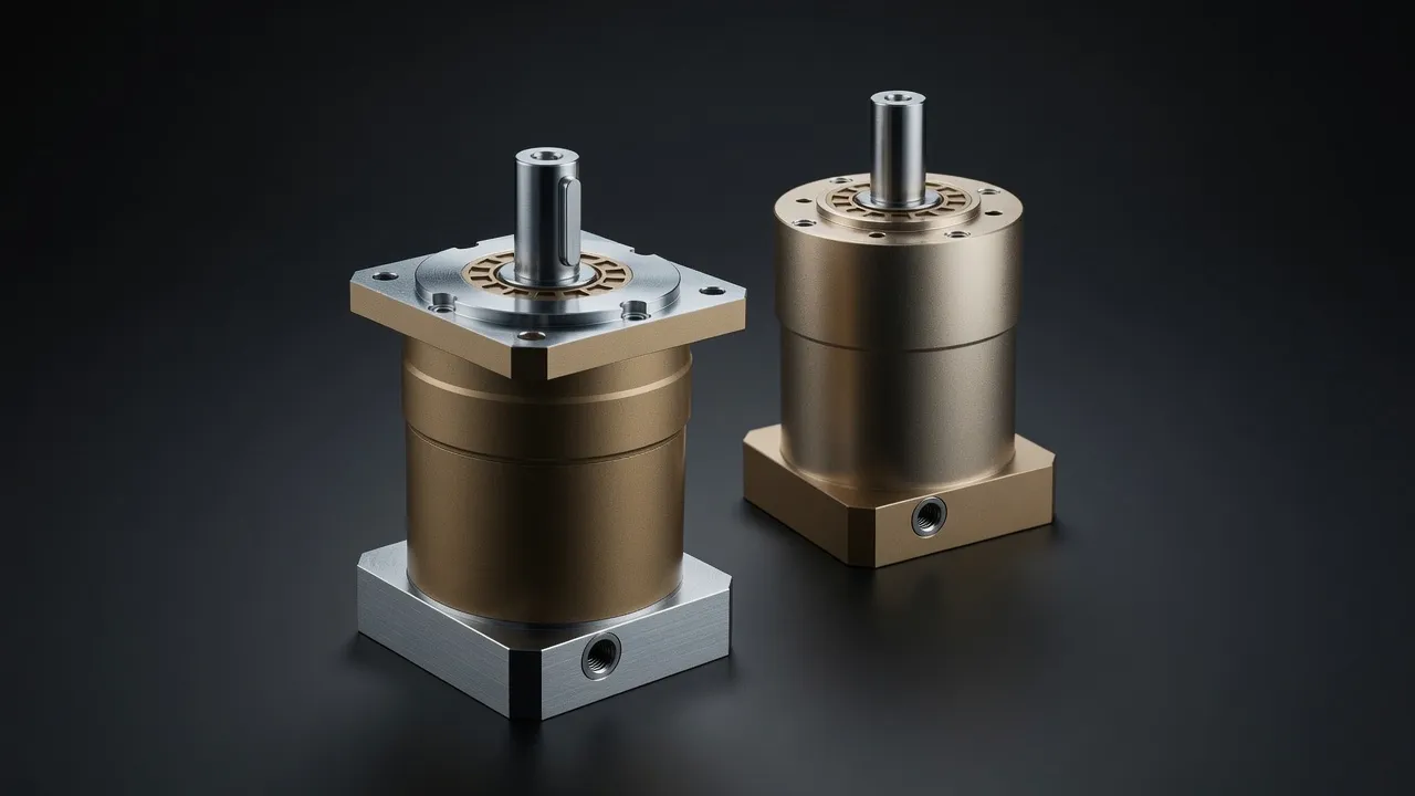
Inertia Matching for Maximum Acceleration
CNC machine productivity depends on rapid traverse speed and fast acceleration between positions. Acceleration is limited by the motor’s ability to accelerate the combined inertia of the rotor, gearbox, coupling, screw, and table mass. Increasing the gearbox ratio reduces the reflected inertia of the screw and table (by the square of the ratio) but also reduces the table speed for a given motor speed. The optimum ratio balances these two effects to minimise the total cycle time across the combination of rapid traverse, acceleration/deceleration, and cutting feed requirements.
The AB115 high-precision planetary series achieves the torsional stiffness (38 N·m/arc-min) and backlash (<3 arc-min) required for 5-axis machining centre axis drives. The AB142 series handles the higher torque requirements of large machining centres and heavy-duty gantry systems where table mass exceeds 2 000 kg.
Thermal Management During Long Machining Cycles
CNC machines running extended production cycles (overnight unmanned operation) generate heat in the axis drive gearboxes throughout the cycle. Temperature rise in the gearbox causes thermal expansion of the gearbox housing and shafts, which changes the effective axis zero position (the thermal offset). On a ball screw axis, a 10°C temperature rise in the gearbox causes the screw bearing block to expand approximately 0.003 mm per degree per 100 mm of screw length. For a 1 000 mm long axis, thermal growth of 0.03 mm per degree means a 30°C temperature rise from cold start to thermal equilibrium produces 0.9 mm of thermal drift — completely unacceptable for precision work. CNC machining centres compensate for this through linear scale feedback (position is measured at the table rather than inferred from motor encoder) or through thermal compensation algorithms.
Frequently Asked Questions
Speak with a Planetary Drive Specialist
Share your torque requirement, ratio, and application environment — our team at Condell Park NSW returns a sized recommendation and stock check within one business day. No obligation.