The yaw drive on a wind turbine rotates the entire nacelle — gearbox, generator, rotor, and all — around the vertical tower axis to face the wind. A 3 MW turbine nacelle assembly weighs 60–90 tonnes and must rotate smoothly through 360° over the course of a day as wind direction changes, while simultaneously being held rigidly in position during operation to prevent the rotor from yawing sideways under asymmetric wind load. The planetary gearbox in the yaw drive achieves both requirements: high torque for active yaw movement and inherent self-holding when the yaw brake is applied.
Yaw Drive Load Calculation and Gearbox Sizing
The torque required to yaw a nacelle depends on the friction in the yaw bearing, the wind-induced overturning moment on the nacelle (which acts as a restoring or resisting force depending on nacelle geometry), and the inertia of the rotating assembly during yaw acceleration. For a 3 MW turbine, the yaw bearing friction torque alone can reach 500–800 kN·m under maximum rotor thrust conditions. Each of the four to eight yaw drives shares this total equally, giving a per-gearbox output torque requirement of 60–200 kN·m. This is achieved through a compound ratio: the planetary gearbox provides 1:100 to 1:300 combined ratio, and the drive pinion meshes with a large-diameter yaw ring gear (typically 2.5–4.0 m diameter) to give the final mechanical advantage.
Holding Torque and the Role of Self-Locking
During operation, the yaw drives hold the nacelle against wind direction changes while the yaw control system decides whether a yaw correction is needed. The holding function is shared between the yaw brake (a caliper brake on the yaw ring gear or a separate friction disc) and the planetary gearbox self-retention. Unlike worm gears, planetary gearboxes are not inherently self-locking — the efficiency of a planetary stage (typically 96–99%) means that back-drive is easy. The yaw brake provides all of the holding torque; the gearbox provides active yaw positioning only.
| Turbine Size | Nacelle Mass | Yaw Ring Diameter | No. of Yaw Drives | Per-Drive Output Torque |
|---|---|---|---|---|
| 1 MW onshore | 25 t | 2.5 m | 4 | 15–25 kN·m |
| 2 MW onshore | 60 t | 3.2 m | 4–6 | 30–60 kN·m |
| 3 MW onshore | 80 t | 3.8 m | 6–8 | 50–100 kN·m |
| 5 MW offshore | 300 t | 5.0 m | 8–12 | 80–200 kN·m |
| 12 MW offshore | 600 t | 8.0 m | 12–16 | 150–400 kN·m |
Per-drive output torque = total yaw torque ÷ number of drives. Verify with nacelle mass and yaw bearing friction data.
Cable Wind-Up and Yaw Counter Management
Wind direction rarely performs neat oscillations around a fixed bearing — it tends to shift gradually in one direction over hours, causing the nacelle to slowly accumulate yaw angle in the same direction. The power and control cables running up through the tower twist as the nacelle yaws, and if twist accumulates beyond ±3 to ±4 full rotations (±1 080° to ±1 440°), the cables can be damaged. Modern yaw control systems include a twist counter that triggers an automatic cable unwind manoeuvre when the accumulated twist approaches the limit — the turbine shuts down, unwinds the cable by rotating the nacelle in the appropriate direction, then restarts. The yaw drive must be capable of executing this unwind at a controlled speed while the rotor is stationary, which means operating against the yaw bearing friction with no aerodynamic driving force. The gearbox must be sized for this condition, which can be the worst-case static friction scenario.
Gear Material and Surface Treatment for 20-Year Life
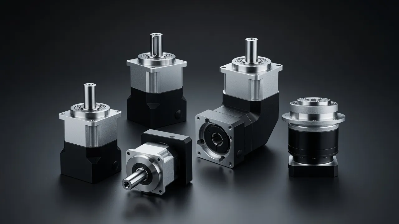
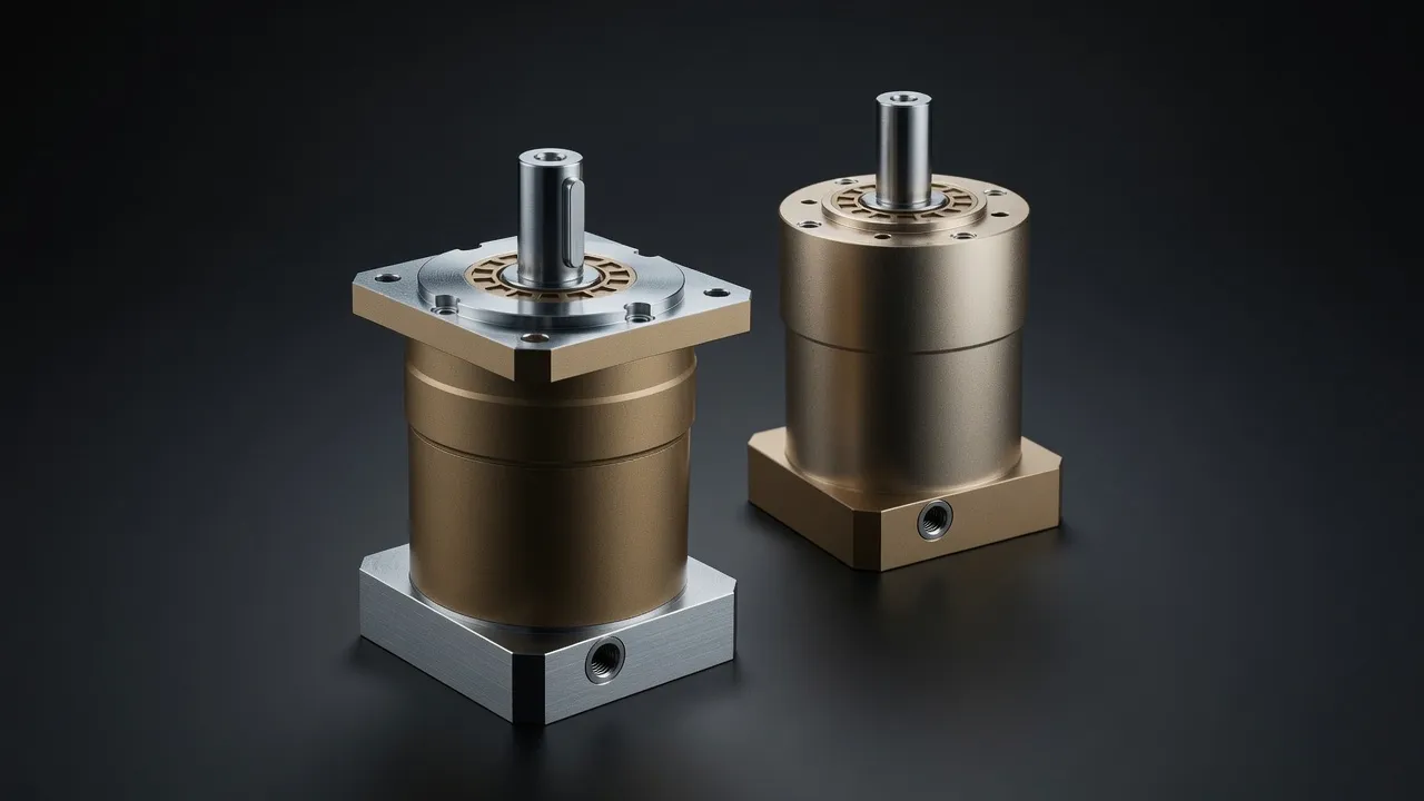
Yaw drive planetary gears are subject to relatively few load cycles compared with the main gearbox or pitch drives — a yaw correction occurs perhaps 50–100 times per day, and each correction involves a few degrees of pinion rotation. The gear teeth experience high peak contact stress with few fatigue cycles, which favours through-hardened gears with generous safety factors over the carburised and ground gears used in high-cycle applications. The EPX heavy planetary gearbox with through-hardened 20CrMnMo steel gears and phosphate surface treatment suits yaw drive applications where installation occurs in remote locations and local gear repair is not feasible. The EPB high-precision torque planetary series is an alternative for applications requiring tighter backlash control for yaw position monitoring feedback systems.
Yaw System Integration and Control
The yaw drive gearbox integrates with the turbine control system through a position encoder on the gearbox output shaft or on the yaw ring gear. The controller calculates the wind vane average direction over a rolling 5–10 minute window and commands a yaw correction when the nacelle is misaligned by more than 5°–15° from the wind. The yaw rate (typically 0.5°/second to 1°/second) is limited to avoid gyroscopic loads on the main bearing from rapid yaw acceleration. The gearbox must respond smoothly within this speed range — planetary gearing achieves this without jerking because there is no backlash-induced stick-slip at the typical yaw operating torques.
For comparable precision planetary drives used in antenna positioner applications — which share the requirement for smooth slow-speed rotation of a heavy structure against variable wind load — the VRV040 servo-grade precision worm gearbox provides an interesting comparison of alternative gear architectures for this type of positioning duty.
Frequently Asked Questions
Speak with a Planetary Drive Specialist
Share your torque requirement, ratio, and application environment — our team at Condell Park NSW returns a sized recommendation and stock check within one business day. No obligation.