
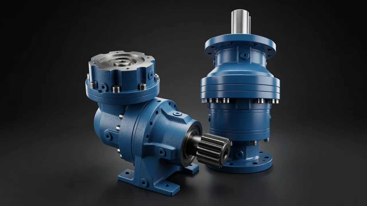
Industrial robot joints are among the most demanding applications for any compact planetary gearbox — each joint must deliver high torque, maintain sub-arc-minute positioning accuracy, survive millions of positioning cycles over a 10-year robot service life, and do all of this in a package small enough to fit within the robot link cross-section without compromising the robot’s reach or payload envelope. The progression from the wrist joints (light load, small diameter, high speed) to the base rotation joint (heavy load, large diameter, lower speed) encompasses almost the full range of precision planetary gearbox specifications in a single machine.
Joint-by-Joint Load Analysis for a 6-Axis Robot
A six-axis robot arm has six revolute joints, numbered from base (J1) to wrist (J6). The load at each joint consists of the torque from the weight of all downstream links and the payload, combined with the dynamic torque from acceleration and deceleration of those masses. J1 (base rotation) carries the full weight of the arm and payload as a moment arm — for a robot with 5 kg payload and 50 kg arm weight, J1 may need to deliver 500–1 000 N·m. J6 (tool rotation) needs only 10–30 N·m for the same robot. This 30:1 torque variation drives the use of different gearbox frame sizes and series across the joints.
| Joint | Function | Typical Torque (5 kg payload robot) | Gearbox Series | Ratio |
|---|---|---|---|---|
| J1 | Base rotation | 500–1 000 N·m | AB180 or AB220 | 100:1–160:1 |
| J2 | Shoulder (main lift) | 400–800 N·m | AB142 or AB180 | 80:1–120:1 |
| J3 | Elbow | 200–400 N·m | AB115 or AB142 | 60:1–100:1 |
| J4 | Forearm rotation | 80–150 N·m | AB090 or AB115 | 50:1–80:1 |
| J5 | Wrist pitch | 40–80 N·m | AB060 or AB090 | 40:1–60:1 |
| J6 | Tool rotation | 10–30 N·m | AB042 or AB060 | 20:1–50:1 |
Torque values are indicative for a 6-axis articulated robot with 5 kg payload and 800 mm reach.
Positioning Accuracy Over Millions of Cycles
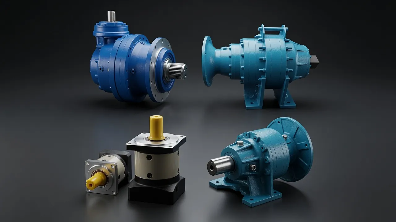
A welding robot in an automotive plant completes 200 000–500 000 positioning cycles per year. Over a 10-year service life, each joint gearbox executes 2–5 million cycles. The backlash specification at installation (typically 1–3 arc-minutes) must remain within the acceptable range throughout this service life — gradual tooth wear increases backlash as the robot ages, eventually degrading positioning accuracy to the point where weld seam location error becomes visible. Monitoring the positioning repeatability (repeat accuracy) of a robot over time is the standard method for detecting approaching end-of-life in the joint gearboxes.
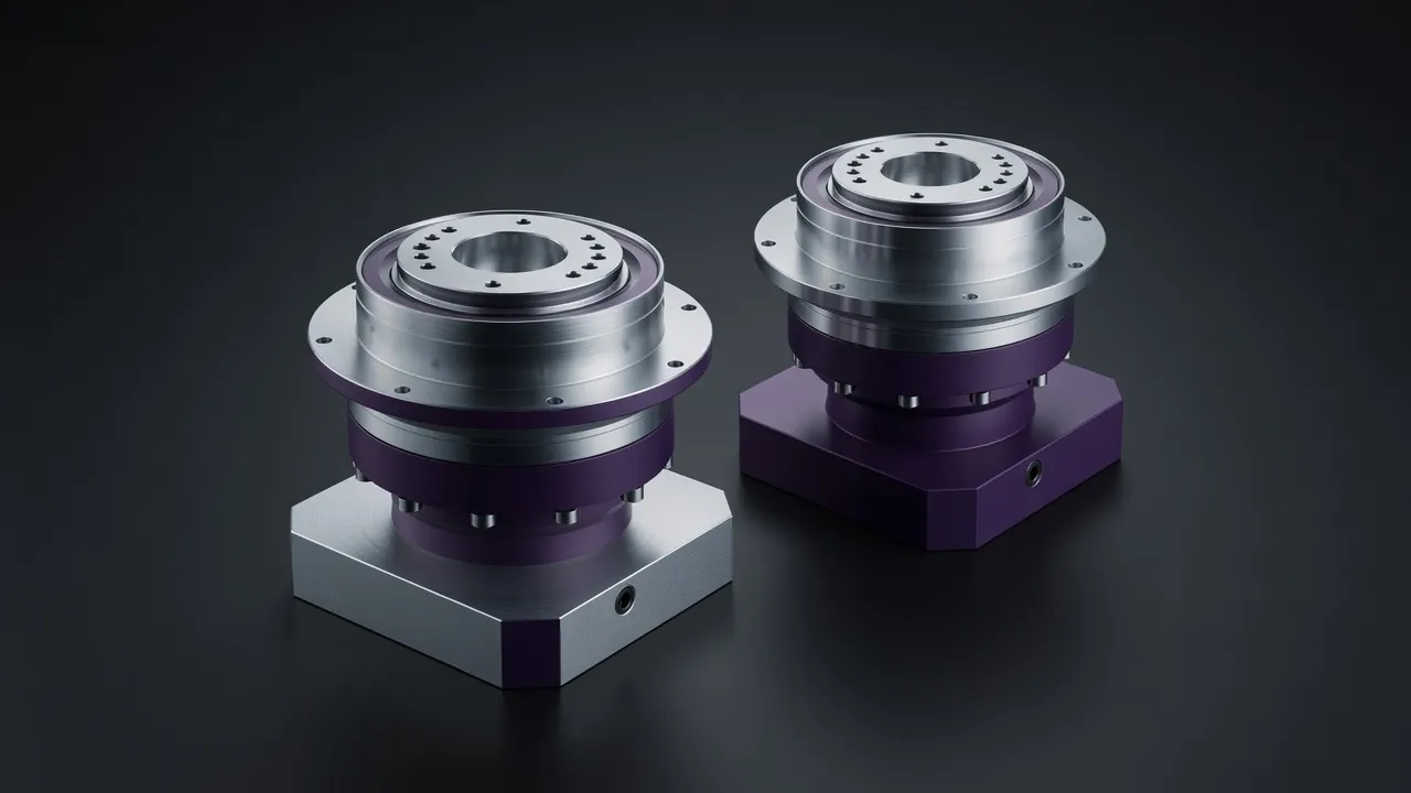
The AB060 series with preloaded sun gear assembly maintains backlash below 3 arc-minutes throughout its service life by using a spring-preloaded sun gear that maintains mesh contact regardless of wear-induced tooth face reduction. The AB090 series applies the same principle in a higher-torque frame for J3–J4 shoulder and elbow joints.
Torsional Stiffness and Path Accuracy in Motion
Positioning accuracy is measured with the robot stationary — it tells you how precisely the robot can reach a target point. Path accuracy measures how closely the robot follows a programmed path during continuous motion. Poor path accuracy means the robot deviates from a straight-line or circular path during welding, painting, or dispensing, producing non-uniform results. Path accuracy is limited by the torsional compliance of the joint gearboxes: when the motor accelerates, the gearbox twists slightly, allowing the motor to advance without the load following immediately. A gearbox with 7 N·m/arc-minute torsional stiffness deflects 1 arc-minute under 7 N·m of torque — in a J1 joint at 800 mm reach, this produces 0.23 mm of TCP (tool centre point) path error.
Heat Generation and Continuous Duty Rating
A continuously operating welding robot with a 60% duty cycle generates heat in every joint gearbox proportional to the power loss. For the J1 gearbox at 500 N·m, 100:1 ratio, running at 1 500 rpm input (15 rpm output), input power is 500 × 2π × 15 ÷ 60 = 785 W. At 97% efficiency, heat generation is approximately 24 W. This is well within the natural convection cooling capacity of the gearbox housing. However, at higher input speeds (3 000 rpm) or higher torque fractions (90% of rated), heat generation increases proportionally and housing temperature should be monitored to ensure it stays below 80°C.
For comparable precision servo drive requirements in high-cycle industrial applications, the VRV030 precision worm gearbox for industrial robots provides an alternative drive architecture worth evaluating for applications where the worm’s self-holding property adds value alongside the precision positioning requirement.
Frequently Asked Questions
Speak with a Planetary Drive Specialist
Share your torque requirement, ratio, and application environment — our team at Condell Park NSW returns a sized recommendation and stock check within one business day. No obligation.