
The swing drive on a hydraulic excavator rotates the entire upper structure — boom, arm, bucket, cab, and counterweight — around the vertical slew axis above the undercarriage. A 20-tonne excavator’s upper structure weighs approximately 12 tonnes and must swing through 360° of arc repeatedly throughout the working day, accelerating from rest to full swing speed and decelerating back to rest on every cycle. The planetary gearbox in the swing drive must produce the torque to accelerate this inertia quickly (fast swing speed improves productivity), hold position precisely during digging (the bucket must not drift during crowd force application), and survive decades of high-cycle duty in construction site conditions.
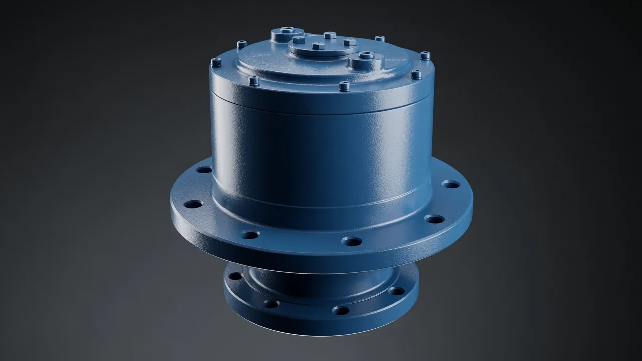
Swing Drive Torque and Inertia Calculation
The peak swing torque has two components: the acceleration torque (to spin the upper structure up to swing speed) and the centrifugal restoration torque (from the offset centre of gravity of the loaded bucket). For a 20-tonne excavator with a 12-tonne upper structure, a 3 m upper structure radius of gyration, and a target angular acceleration of 0.5 rad/s²: acceleration torque = I × α = (12 000 × 3²) × 0.5 = 54 000 N·m. With a 4-planet planetary gearbox at 1:50 ratio, the motor side torque is 54 000 ÷ 50 = 1 080 N·m — within the range of a hydraulic swing motor paired with a WPA 155 or 175 equivalent planetary gearbox.
| Excavator Class | Upper Structure Mass | Target Swing Speed | Peak Swing Torque | Gearbox Output Torque | Ratio |
|---|---|---|---|---|---|
| Mini, 3–5 t | 2 t | 10 rpm | 8 000 N·m | 8 000 N·m direct | 1:50 to motor |
| Mid, 10–15 t | 7 t | 8 rpm | 25 000 N·m | 25 000 N·m direct | 1:80 |
| Standard, 20–30 t | 14 t | 7 rpm | 54 000 N·m | 54 000 N·m direct | 1:100 |
| Large, 50–70 t | 35 t | 5 rpm | 120 000 N·m | 120 000 N·m | 1:150 |
| Mining, 100+ t | 80 t | 4 rpm | 300 000 N·m | 300 000 N·m | Custom |
Gearbox output torque = slew ring mesh torque from pinion on ring gear. Ratio is from motor to planetary output.
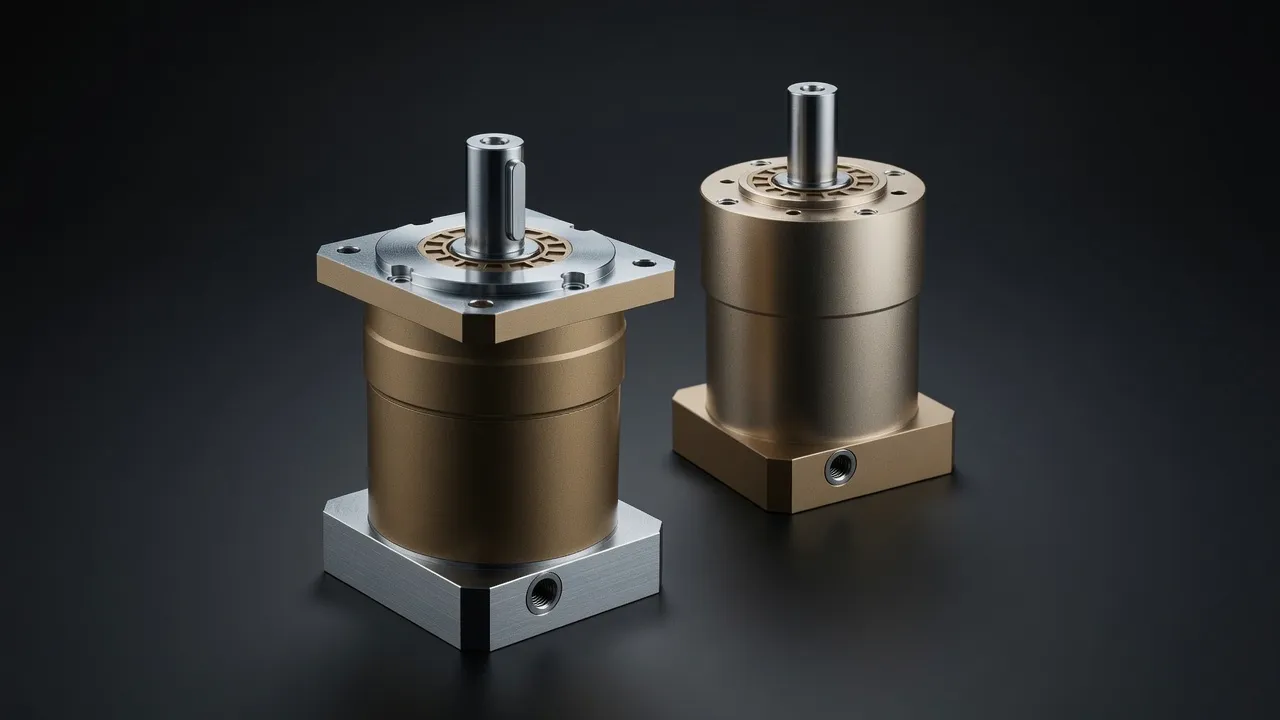
Multi-Stage Planetary Architecture for Swing Drives
Excavator swing drives typically use two or three planetary stages to achieve the overall ratio of 50:1 to 150:1. Each stage provides 4:1 to 7:1 ratio. The stages are integrated in a compact vertical stack — the swing motor mounts on top, the output pinion meshes with the slew ring gear at the bottom, and the planetary stages are sandwiched between. The planet carrier of each stage becomes the input to the next stage, and the ring gears of all stages are fixed to the outer housing. The compactness of this arrangement allows the entire swing gearbox (motor, three planetary stages, output pinion) to fit within 400–500 mm of vertical height — essential for maintaining cab height and boom geometry.
Swing Bearing and Output Arrangement
The planetary gearbox output connects to a small spur or helical pinion that meshes with the large slew ring gear around the excavator’s undercarriage. The slew ring gear (typically 1.0–2.0 m diameter) provides the final mechanical advantage — the overall ratio from motor to upper structure is the product of the planetary ratio and the slew ring gear reduction. The swing bearing (a large-diameter slewing ring bearing) supports the upper structure weight and the swing torque simultaneously. The planetary gearbox does not support the upper structure load directly; it only transmits the swing torque through the pinion-ring mesh.
The EPX heavy planetary series provides the case-hardened alloy steel planet gears and high shock load ratings required for excavator swing applications. The EPB high-precision torque planetary is an alternative for smaller excavators where the swing position must be monitored accurately for precise grading or demolition work.
Hydraulic Motor Integration and Swing Brake
The swing motor on most excavators is a hydraulic axial piston motor — high pressure hydraulic oil drives the pistons, which rotate the output shaft. The planetary gearbox connects directly to the hydraulic motor output shaft through a splined coupling or bolted flange. A spring-applied hydraulic-released swing brake (park brake) is mounted between the motor and the gearbox — when the operator releases the swing lever, the pilot pressure to the brake drops and the spring clamps the motor shaft, holding the upper structure in position. The planetary gearbox must transmit the braking torque from the stationary motor through to the slew ring without any backlash-induced jolting as the brake engages. For reference on alternative high-torque compact drives in construction machinery, the RR528/RR577 heavy-duty worm gearbox for metallurgy demonstrates the heavy industrial housing and seal standards applicable to similar demanding outdoor environments.
Frequently Asked Questions
Speak with a Planetary Drive Specialist
Share your torque requirement, ratio, and application environment — our team at Condell Park NSW returns a sized recommendation and stock check within one business day. No obligation.