
The drive axle planetary reducer on a wheel loader is the final mechanical stage that converts transmission torque into the tractive force that pushes the machine into a pile, carries the bucket to the dump point, and backs the machine away for the next pass. Wheel loaders in quarrying, port operations, and construction across Australia operate in some of the most abrasive environments on earth — crushing granite aggregate, loading iron ore, pushing sand and limestone — and the final drive planetary gearbox must deliver reliable service across a 10 000–15 000 hour operating life with only oil changes and seal replacements as maintenance.
Wheel Loader Duty Cycle and Torque Demands
A wheel loader in a quarry operates on a repetitive cycle: approach pile at 10–15 km/h, decelerate and engage the pile at 3–5 km/h, crowd the bucket (high torque, low speed), reverse out of the pile, travel to the crusher or truck at 15–25 km/h, dump, return to pile. This cycle — typically 40–90 seconds — repeats 400–600 times per day. The highest torque event is the pile engagement: the machine’s full weight (traction control) is applied to the drive wheels at 3–5 km/h, with the hydraulic lift and crowd cylinders simultaneously working to fill the bucket. This produces the maximum simultaneous wheel torque and bucket crowd force that the machine is capable of generating.
| Loader Class | Machine Mass | Bucket Crowd Force | Max Wheel Torque | Axle Ratio | Final Drive Torque |
|---|---|---|---|---|---|
| Small (2–4 t payload) | 10 t | 80 kN | 15 000 N·m total | 12:1 | 30 000 N·m per axle |
| Medium (4–7 t payload) | 18 t | 120 kN | 25 000 N·m | 15:1 | 50 000 N·m per axle |
| Large (7–12 t payload) | 30 t | 180 kN | 40 000 N·m | 18:1 | 80 000 N·m per axle |
| Ultra (12–20 t payload) | 60 t | 250 kN | 70 000 N·m | 22:1 | 150 000 N·m per axle |
| Mining (20–40 t payload) | 120 t | 400 kN | 120 000 N·m | 25:1 | 300 000 N·m per axle |
Final drive torque = wheel torque × final drive ratio. Per axle = 2 × per wheel value.
Hub-Integrated Planetary Design
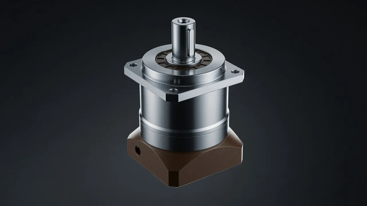
Wheel loader final drives are integrated within the wheel hub, similar to excavator travel drives. The axle shaft drives the sun gear; the ring gear is fixed to the axle housing (and through it, to the machine frame); the planet carrier rotates and connects to the wheel hub. This coaxial design eliminates external chain or gear stages and provides the largest possible ground clearance by keeping all drivetrain components within the wheel envelope. The planet gears are typically arranged in a 3-planet or 4-planet configuration; 4-planet arrangements distribute the load more evenly and are preferred for higher-torque applications where the contact stress on a 3-planet arrangement exceeds the tooth safety factor.
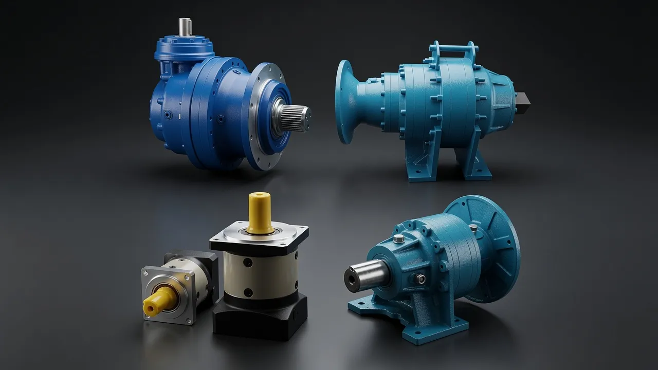
The EPX heavy planetary series demonstrates the gear case hardening depth, planet pin diameter, and housing wall thickness proportions used in wheel loader final drives applied to industrial planetary gearboxes. For precision electric wheel loader development projects, the EPG two-stage precision planetary provides the closed-loop torque control capability needed for traction control on electric wheel loaders.
Articulation Joint and Driveshaft Integration
Wheel loaders steer by articulating the front and rear chassis around a central vertical joint — the front and rear axles are on separate chassis halves that pivot relative to each other. Power from the transmission reaches both axles through articulating driveshafts (propeller shafts with universal joints or constant-velocity joints at the articulation pivot). The front axle planetary final drives must therefore accommodate angular misalignment from the suspension (on machines with oscillating front axles) in addition to the high torque loads. The axle housing-to-hub interface must be sealed against both the axle oil and the external environment — a failure at this interface allows axle oil to contaminate the hub oil and vice versa, with potentially catastrophic consequences for gear and bearing life.
Tyre Spin and Traction Management
Wheel loaders equipped with limited-slip differentials or electronic traction control engage the differential lock when one wheel begins to spin in loose material. At full differential lock, all tractive force passes through the loaded wheel’s final drive — potentially doubling the torque seen by that single hub’s planetary gearbox. This must be within the final drive’s rated peak torque capacity. If the machine is also fitted with aggressive terrain tyres that prevent tyre spin even at high differential torque, the final drive must absorb the full locked-differential torque indefinitely — a much more severe condition than momentary slip. Wheel loader specification documents should clarify whether the differential lock is momentary or sustained in operation, as this significantly affects the final drive service factor.
For heavy-duty outdoor drive applications in comparable earthmoving environments, the RR528 heavy-duty worm gearbox provides a reference point for the housing and sealing standards applicable to severe outdoor industrial machinery environments.
Frequently Asked Questions
Speak with a Planetary Drive Specialist
Share your torque requirement, ratio, and application environment — our team at Condell Park NSW returns a sized recommendation and stock check within one business day. No obligation.