
An in-wheel motor with a planetary reducer is the most compact and direct form of electric vehicle propulsion: the motor and gearbox are housed entirely within the wheel hub, driving the wheel directly without any driveshaft, differential, or half-shaft. This architecture eliminates the mechanical losses and packaging complexity of a central motor and long driveshafts, enables independent torque control at each wheel for traction control and active torque vectoring, and frees up the vehicle underbody for battery or cargo space. The planetary gearbox that makes this possible must fit within the wheel rim while still providing the ratio and torque density to match the motor output to the wheel speed.
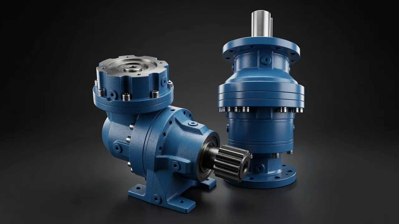
Packaging Constraints of In-Wheel Drive
A 16-inch (406 mm) rim leaves a usable internal diameter of approximately 300–340 mm after accounting for the tyre bead seat and the structural rim. An 18-inch rim allows 360–400 mm. The planetary reducer — ring gear, planets, sun gear, and carrier — must fit within this diameter while delivering the required torque to the wheel hub. The ring gear is typically integrated with the wheel hub structure, eliminating a separate housing component and reducing weight. The motor stator mounts to the suspension upright, and the motor rotor connects to the sun gear input shaft of the planetary stage.
Ratio and Torque Requirements for In-Wheel Applications
| Vehicle Type | Target Wheel Torque | Motor Peak Torque | Required Ratio | Motor Peak RPM | Wheel Top Speed |
|---|---|---|---|---|---|
| Passenger car, 18″ rim | 2 000 N·m | 250 N·m | 8:1 | 12 000 rpm | 210 km/h |
| Electric bus, 22.5″ rim | 15 000 N·m | 500 N·m | 30:1 | 6 000 rpm | 100 km/h |
| Forklift, heavy-duty | 30 000 N·m | 800 N·m | 37:1 | 3 000 rpm | 25 km/h |
| Mining haul truck, giant | 500 kN·m | 5 000 N·m | 100:1 | 1 500 rpm | 50 km/h |
| AGV warehouse robot | 500 N·m | 50 N·m | 10:1 | 6 000 rpm | 15 km/h |
Wheel torque = motor peak torque × ratio × efficiency. Top speed = motor rpm ÷ ratio × wheel circumference.
Unsprung Mass: The Critical Design Constraint
In conventional vehicle dynamics, the mass of components that move with the wheel — the wheel, tyre, brake disc, hub, and half-shaft — is called unsprung mass. High unsprung mass worsens ride quality and handling because the wheel cannot follow road irregularities as quickly when it is heavy. Adding a motor and planetary gearbox to the wheel significantly increases unsprung mass — a typical in-wheel motor system adds 15–25 kg per corner compared with a central motor arrangement. This is the primary reason in-wheel motors have not become mainstream in passenger cars despite their conceptual elegance: the ride and handling compromise is significant on normal road surfaces.
The compromise is more acceptable in applications where ride quality is less critical — commercial vehicles, buses, agricultural machinery, and industrial vehicles. The EPB high-precision torque planetary gearbox with its high torque density (high torque per kilogram of gearbox mass) minimises the unsprung mass penalty, and the EPF economy flange output planetary series provides a cost-effective option for commercial vehicle in-wheel applications where precision is less critical than torque capacity and durability.
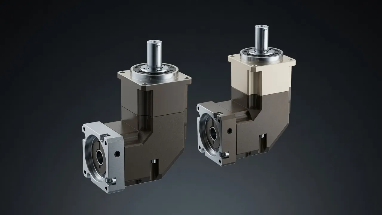
Bearing Arrangement for Hub Integration
The planetary reducer in an in-wheel motor must serve double duty: it provides the gear ratio, and its output bearing arrangement supports the wheel load. A conventional vehicle wheel bearing consists of a double-row tapered roller bearing or angular contact ball bearing that carries both radial load (vehicle weight) and axial load (cornering force). The planetary output carrier serves as the inner race of this bearing, with the ring gear or hub housing serving as the outer race. This integration saves weight and axial length but requires careful design to ensure the bearing preload is maintained through the full temperature range — thermal expansion of aluminium hub components relative to steel gears changes the bearing preload as the system heats up during driving.
Sealing and Environmental Protection
An in-wheel motor and planetary reducer are exposed to road splash — mud, water, salt, and tyre spray — that is far more aggressive than the environment seen by a nacelle-mounted motor or a gearbox in a machine room. IP67 is the minimum sealing requirement; IP69K (high-pressure wash-down at 80°C) is specified by some truck and bus manufacturers who pressure-wash vehicles regularly. The seal must also handle the constant rotation of the wheel and the articulation of the suspension — the seal interface between the rotating hub and the fixed suspension upright must accommodate 5–10 mm of axial and radial movement from suspension travel without compromising the IP rating. For comparable sealing challenges in marine environments, the HSRV stainless steel worm gearbox demonstrates the sealing approach used in submerged or wash-down exposed drive applications.
Frequently Asked Questions
Speak with a Planetary Drive Specialist
Share your torque requirement, ratio, and application environment — our team at Condell Park NSW returns a sized recommendation and stock check within one business day. No obligation.