
The hoist planetary gearbox on a crane is the component that, when it fails, results in a load drop — one of the most dangerous events in any industrial setting. The engineering requirements for a crane hoist planetary gearbox therefore start not with a torque calculation but with a safety classification: the gearbox must be designed to a specific mechanism class (M1 through M8 in the FEM and ISO standards) that captures the duty cycle, the spectrum of load levels, and the required design life in operating hours. Only after establishing the safety classification does the torque and ratio selection follow — and the safety factor on gear tooth strength must meet the classified requirement, not just the calculated running torque.
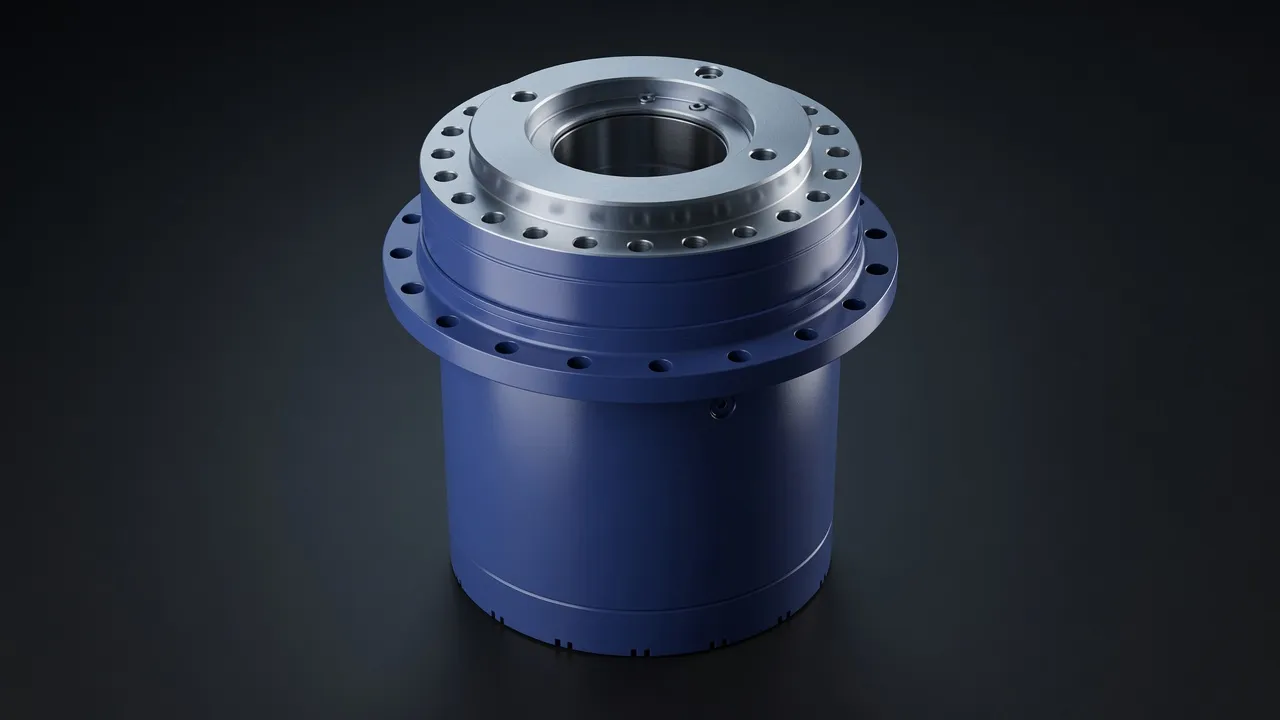
Mechanism Classification and Its Effect on Gearbox Design
The FEM/ISO mechanism class system classifies crane hoists based on two parameters: the total number of operating cycles over the design life (load spectrum class) and the ratio of time spent at maximum load to total operating time (utilisation class). A workshop crane lifting 5 tonnes at maximum 10% of the time falls in M3–M4; a harbour crane lifting containers at 90% of its maximum load continuously is M7–M8. The mechanism class determines the minimum design safety factor for gear tooth bending stress and contact stress, and the minimum bearing L10 life in hours. Getting the mechanism class wrong by two steps (M4 instead of M6) can reduce the gearbox design life by a factor of 5–10.
| Mechanism Class | Typical Application | Design Life (hours) | Utilisation at Max Load | Gear Safety Factor (tooth root) |
|---|---|---|---|---|
| M2 | Occasional use maintenance crane | 400 | Rarely (<12.5%) | ≥1.4 |
| M4 | Workshop overhead crane | 3 200 | Sometimes (25–50%) | ≥1.6 |
| M5 | Manufacturing plant crane | 6 300 | Often (50–63%) | ≥1.8 |
| M6 | Shipyard or heavy plant crane | 12 500 | Often (63–80%) | ≥2.0 |
| M7 | Steelworks charging crane | 25 000 | Frequently (80–100%) | ≥2.2 |
| M8 | Continuous process crane | 50 000 | Very frequent (>80%) | ≥2.5 |
Mechanism classes per FEM 1.001. Design life in working hours at the classified load spectrum.
Rope Drum Drive and Ratio Calculation
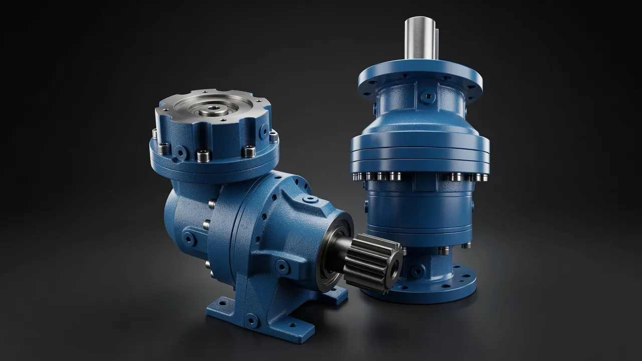
The rope drum connects to the planetary gearbox output shaft. The required gearbox ratio is calculated from the drum speed needed for the target lifting speed: drum speed = lifting speed ÷ (rope layers × π × drum core diameter × rope reeving factor). For a 10 m/min lift speed with double reeving (rope speed = 2 × drum peripheral speed), 250 mm drum core diameter, and one rope layer: drum speed = 10 000 ÷ (1 × π × 250 × 2) = 6.4 rpm. From a 1 440 rpm motor: required ratio = 1 440 ÷ 6.4 = 225:1. A three-stage planetary gearbox providing approximately 5:1 × 5:1 × 9:1 = 225:1 achieves this in a single housing.
Self-Locking and Holding Brake
Planetary gearboxes do not self-lock under back-drive — a suspended crane load back-drives the drum, through the gearbox, and spins the motor unless a positive brake is applied. The crane hoist brake is a spring-applied, electrically released disc or drum brake on the motor shaft (upstream of the gearbox). The brake must hold the maximum suspended load torque at the motor shaft: motor brake torque = drum torque ÷ (gearbox ratio × efficiency). For 10 000 N load at a 200 mm drum radius: drum torque = 2 000 N·m; motor brake torque = 2 000 ÷ (225 × 0.95) = 9.36 N·m. Standard motor brakes rated at 150% of motor nominal torque provide adequate holding margin.
The EPB high-precision torque planetary series provides the tooth safety factors and bearing L10 life ratings needed for crane hoist duty at M4–M6 mechanism classes. The EPX heavy planetary series covers M6–M8 heavy duty cranes in steelworks, harbour operations, and continuous process applications. For reference on comparable drive applications in lifting equipment, the MRV/NMRV standard worm gearbox series demonstrates the torque range covered by alternative gear architectures for lighter lifting applications.
Condition Monitoring in Crane Hoist Gearboxes
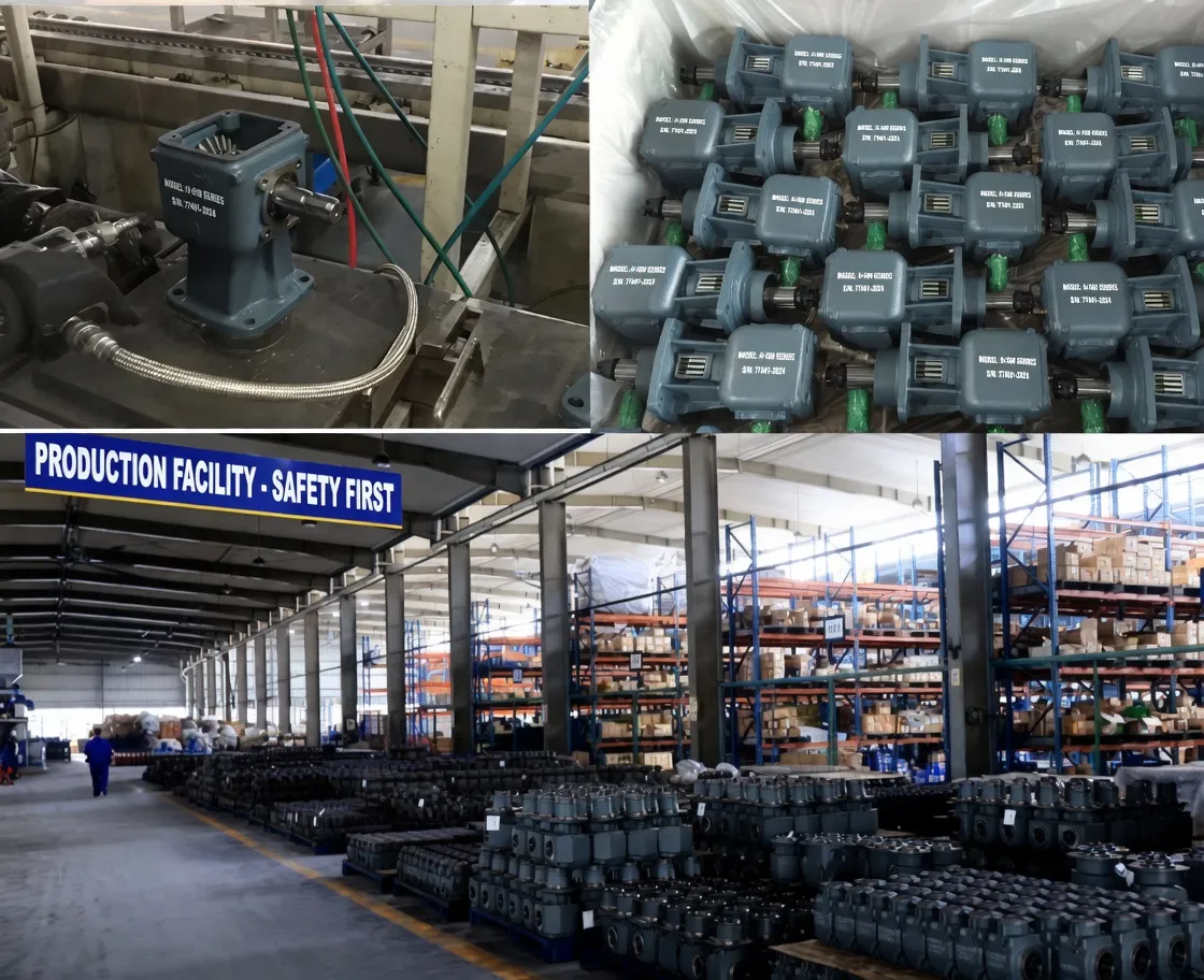
Crane hoist gearboxes in Australian ports, steelworks, and manufacturing plants are required under the relevant AS 4991 crane maintenance standard to undergo periodic inspection. The inspection interval depends on the mechanism class — M2–M3 cranes are inspected every 5 years; M7–M8 cranes are inspected annually or more frequently. Vibration signature analysis, oil particle counting, and magnetic drain plug inspection are the three primary condition monitoring methods applicable to enclosed planetary hoist gearboxes. A hoist gearbox operating in a steelworks environment is also subject to contamination from scale dust and steel particles that enter through the breather — a sealed breather with a desiccant filter is the minimum standard in steelworks crane applications.
Frequently Asked Questions
Speak with a Planetary Drive Specialist
Share your torque requirement, ratio, and application environment — our team at Condell Park NSW returns a sized recommendation and stock check within one business day. No obligation.