
The main gearbox in a wind turbine is the single most mechanically demanding planetary drive in commercial production — a 5 MW offshore turbine rotor turns at 8–12 rpm and must deliver that torque to a generator spinning at 1 200–1 800 rpm, giving an overall ratio of 100:1 to 150:1 inside a nacelle that is both weight-constrained and impossible to service without a crane. Planetary gearboxes achieve this in two or three stages within a housing lighter than any parallel-shaft equivalent, and the load-sharing across three or four planet gears per stage allows torque densities that no single-mesh gear pair can approach.
Why Planetary Architecture Suits Wind Turbine Drives
Three properties make planetary gearing the standard for wind turbine main drives. First, the coaxial input and output shafts allow the rotor shaft and generator shaft to be concentric, which simplifies the nacelle layout and reduces the bending moment on the main bearing. Second, the load is shared equally across three or four planet gears simultaneously — unlike a parallel-shaft gear where one mesh carries the entire torque — so the contact stress per mesh is a fraction of what a single-mesh gear would see at the same torque. Third, planetary stages are inherently compact: the ring gear is the outer housing of the stage, so the gear-set fits within a diameter only slightly larger than the pitch circle of the planets, giving a torque-to-weight ratio two to three times better than helical-bevel configurations at comparable ratios.
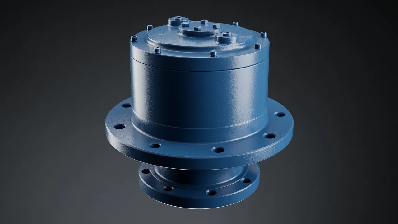
Typical Three-Stage Wind Turbine Gearbox Architecture
Stage 1: Planetary to Planetary
The first stage handles the highest torque and the lowest speed — rotor shaft torque in a 5 MW turbine at rated wind speed reaches 4–5 MN·m. A single planetary stage typically provides a ratio of 1:4 to 1:6, reducing rotor speed from 10 rpm to 50–60 rpm while reducing the torque by the same factor. Planet gear counts of three or four are standard at this stage; some large turbines use six planets to further distribute the contact stress. The planet carrier rotates; the ring gear is fixed to the nacelle structure; the sun gear drives the next stage.
Stage 2: Planetary or Helical
The second stage typically uses a second planetary set (ratio 1:4 to 1:5) or a parallel helical stage to bring speed to 200–350 rpm. The torque has dropped to manageable levels for helical gearing by this point, which is why some manufacturers choose a simpler helical stage here for cost and serviceability reasons. The intermediate shaft between stages 2 and 3 is usually the most accessible part of the gearbox for field inspection, and oil sampling ports at this location are standard practice for condition monitoring.
Stage 3: High-Speed Helical
The final stage is invariably a parallel helical stage because the tooth-contact efficiency at 1 200–1 800 rpm output speed matters greatly for energy yield over a 20-year turbine life, and helical gears deliver 98–99% mesh efficiency at these speeds compared with 85–90% for a planetary stage at the same ratio. The high-speed shaft connecting this stage to the generator is the most failure-prone component in the drivetrain — it spins at generator speed under varying torque and is subject to misalignment-induced bending from thermal growth of the nacelle structure.
| Stage | Type | Input Speed | Output Speed | Ratio | Torque Level |
|---|---|---|---|---|---|
| 1 | Planetary | 10 rpm (rotor) | 50 rpm | 1:5 | Very high (MN·m) |
| 2 | Planetary | 50 rpm | 250 rpm | 1:5 | High (kN·m) |
| 3 | Parallel helical | 250 rpm | 1 500 rpm | 1:6 | Moderate (kN·m) |
| Overall | 3-stage compound | 10 rpm | 1 500 rpm | 1:150 | — |
Illustrative values for a 2 MW onshore turbine. Actual ratios vary by manufacturer and turbine class.
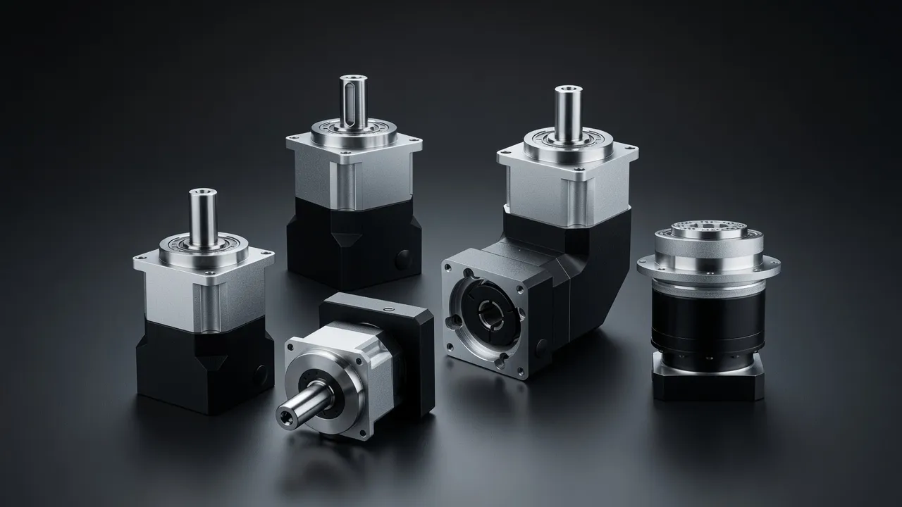
Load-Sharing and Planet Gear Tolerance Requirements
Equal load sharing among planet gears is critical — if one planet carries even 10% more torque than the others, its tooth contact stress rises by 10% and its fatigue life drops by more than 25% (fatigue life is roughly proportional to stress raised to the power of 9 for through-hardened steel). Load sharing depends on manufacturing tolerances of the planet pin positions and planet gear tooth geometry, the stiffness of the planet carrier arms, and the bearing clearances at each planet shaft. The IEC 61400-4 standard for wind turbine gearboxes specifies minimum load distribution factors and their influence on gear-tooth rating.
The EPX heavy planetary gearbox series uses a floating sun gear arrangement where the sun shaft is radially unconstrained, allowing it to centre itself by equalising the tangential forces from all planet meshes simultaneously — this is one of the most effective passive load-sharing mechanisms and is standard in most modern wind turbine gearboxes. The EPG two-stage precision planetary series demonstrates the same principle in a compact industrial drive format, with measured load distribution factors below 1.05 for three-planet configurations — effectively equal sharing to within 5%.
Lubrication System Design for Long Service Life
Wind turbine main gearboxes use forced-circulation oil lubrication with a dedicated pump, filter, cooler, and condition monitoring system — not an oil bath. The pump maintains a continuous oil flow to each planet bearing, sun gear mesh, and ring gear mesh; the cooler (typically an air-oil heat exchanger) maintains oil temperature between 50°C and 70°C regardless of ambient; and the filter system (a 10 µm absolute filter) removes wear particles before they can act as abrasives in the mesh. Oil particle counters with ISO 4406 cleanliness monitoring are standard on turbines above 1 MW, and automatic shutdown is triggered if cleanliness exceeds ISO 16/14/11.
Condition Monitoring and Predictive Maintenance
A wind turbine main gearbox failure at rated speed releases enough energy to destroy the nacelle. The industry response has been a shift from time-based maintenance to condition-based maintenance driven by oil analysis, vibration signature analysis, and acoustic emission monitoring. Vibration sensors on each bearing location detect changes in the vibration signature as tooth surface fatigue begins to develop — typically 4–8 weeks before a tooth actually chips. Oil analysis identifying elevated iron (ring gear and planet gear wear), chromium (bearing wear), and silicon (oil contamination from seal ingress) provides independent confirmation. Modern turbines in NSW wind farms integrate this data into a SCADA system that schedules maintenance based on actual condition rather than calendar intervals, extending gearbox service life and reducing unplanned stops.
Selecting the Right Planetary Drive for Industrial Wind Applications
For smaller wind energy applications — small turbines below 100 kW, test rigs, and wind tunnel drives — the industrial precision planetary series provides the ratio range and torque density without the expense of a custom wind turbine gearbox. Contact the EPB high-precision torque planetary gearbox specification for compact high-torque industrial wind drives. For reference on compatible drive combinations, the PGV planetary gearbox offers a comparison point for precision planetary units in variable-speed drive applications.
Frequently Asked Questions
Speak with a Planetary Drive Specialist
Share your torque requirement, ratio, and application environment — our team at Condell Park NSW returns a sized recommendation and stock check within one business day. No obligation.