
Electric buses in Sydney, Melbourne, Brisbane, and the regional networks being rolled out across NSW represent one of the most demanding duty cycles for any drivetrain component. The drive axle gearbox must handle repeated acceleration events from standstill in stop-start urban routes, sustain continuous output at highway speeds on express services, survive 20-year service lives in outdoor conditions with minimal maintenance, and do all of this while carrying up to 20 tonnes of laden bus mass through Australian urban and regional road conditions that include significant grades, rough road surfaces, and daily extreme temperature swings.
Drive Axle Architecture for Electric Buses
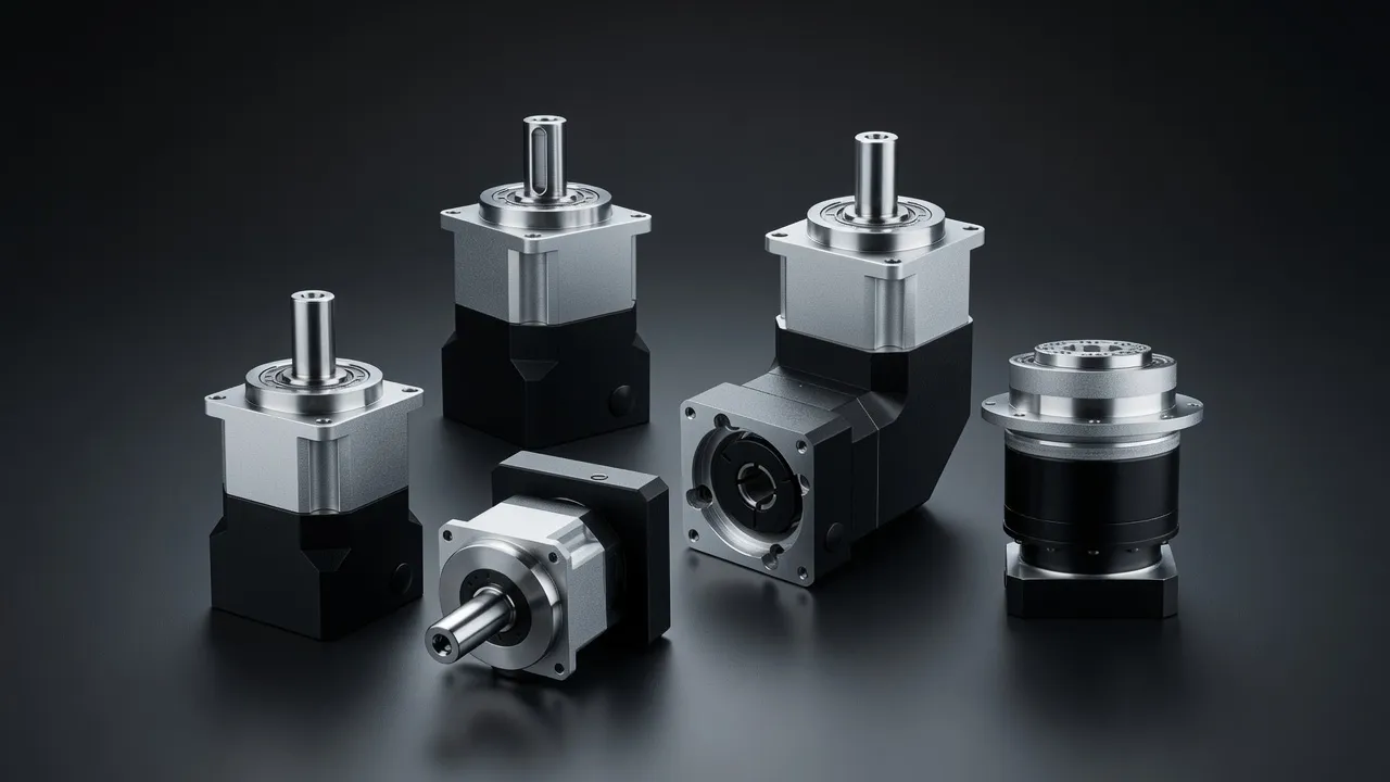
Most electric buses use a central motor driving a conventional live rear axle through a two-speed or single-speed reduction gearbox and a differential. The planetary gearbox replaces the conventional engine gearbox and clutch, providing a fixed reduction ratio from the motor to the differential input. Some electric bus designs eliminate the differential by using two independently controlled in-wheel motors — one per drive wheel — with torque vectoring control replacing the differential function electronically. Both approaches are in active service across the Australian electric bus fleet.
Torque Requirements for Bus Duty
| Operating Condition | Required Wheel Torque | Speed | Gearbox Output Torque (ratio 10:1) | Motor Torque |
|---|---|---|---|---|
| Full acceleration, GVM 20t | 38 000 N·m per axle | 0–20 km/h | 3 800 N·m | 380 N·m |
| Grade climbing, 8%, GVM 20t | 20 000 N·m per axle | 20–40 km/h | 2 000 N·m | 200 N·m |
| Urban cruise, 60 km/h | 4 000 N·m per axle | 60 km/h | 400 N·m | 40 N·m |
| Highway, 100 km/h | 3 500 N·m per axle | 100 km/h | 350 N·m | 35 N·m |
| Emergency braking (regen) | −25 000 N·m per axle | 100–0 km/h | −2 500 N·m | −250 N·m |
10:1 gearbox ratio assumed. Actual ratio depends on motor peak speed and target vehicle top speed.
Why Planetary Gearing Suits Bus Drive Applications
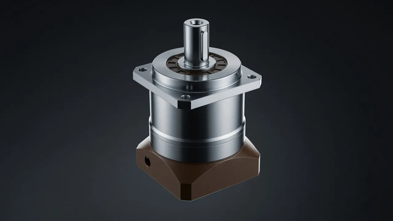
Bus drive axle gearboxes require very high torque in a compact axle-width package — the gearbox must fit within the axle housing while leaving adequate clearance for road wheels and suspension geometry. Planetary gearing achieves the required torque in a coaxial, compact format that parallel-shaft gearing cannot match within the axle dimensional constraints. A two-stage planetary providing 10:1 total ratio occupies less than 300 mm of axle length, compared with 600–800 mm for an equivalent parallel-shaft reducer. This axle-length saving translates directly to suspension design freedom and interior floor space.
The EPX heavy planetary gearbox series with its case-hardened alloy steel gears and high torque density suits bus drive axle applications requiring maximum durability. For precision servo bus applications — autonomous bus platforms with encoder-based torque control — the EPG two-stage precision planetary series provides the positional accuracy and low-backlash performance that precision autonomous control systems require.
Duty Cycle and Thermal Management
Urban bus routes impose a severe duty cycle on the drive axle gearbox: every bus stop requires full-throttle acceleration from standstill, followed by sustained cruise, followed by regenerative braking. A route with stops every 300 m at 30 km/h average speed cycles the drivetrain approximately 100 times per hour — equivalent to a 25% duty cycle at peak torque. This is substantially more demanding than most industrial gearbox applications, which is why bus drive gearboxes use forced-circulation oil cooling rather than oil-bath splash lubrication. Oil temperature is maintained at 60–80°C by a water-cooled oil heat exchanger integrated with the vehicle thermal management system.
Service Life and Reliability Expectations
Public transport operators in NSW specify drive axle gearboxes for a minimum 1 000 000 km service life — approximately 20 years at 50 000 km/year for a metro bus. Over this distance, a single planet gear tooth experiences approximately 5 × 10⁹ load cycles. Achieving this fatigue life requires case-hardened gears with a case depth of at least 1.0–1.5 mm, shot-peened tooth roots to introduce compressive residual stress, and surface roughness below Ra 0.4 µm to maintain hydrodynamic lubrication at low sliding speeds. The PGV planetary gearbox specification demonstrates the material and process standards that comparable heavy-duty planetary applications demand.
Frequently Asked Questions
Speak with a Planetary Drive Specialist
Share your torque requirement, ratio, and application environment — our team at Condell Park NSW returns a sized recommendation and stock check within one business day. No obligation.