
Rolling mills in steel, aluminium, and copper production subject their drive gearboxes to the highest continuous torque density of any metal manufacturing application — the roll separating force on a hot strip mill can reach 20–50 MN between the work rolls, transmitted to the drive shafts as torques that require multi-stage planetary gearboxes with planet gears the size of car wheels. The planetary architecture’s coaxial torque sharing across multiple planet gears is the only practical way to achieve the required torque density within the physical constraints of a rolling mill stand, and the quality of gear manufacture and heat treatment determines whether the mill produces steel for a decade or requires an emergency reline within a few years of commissioning.
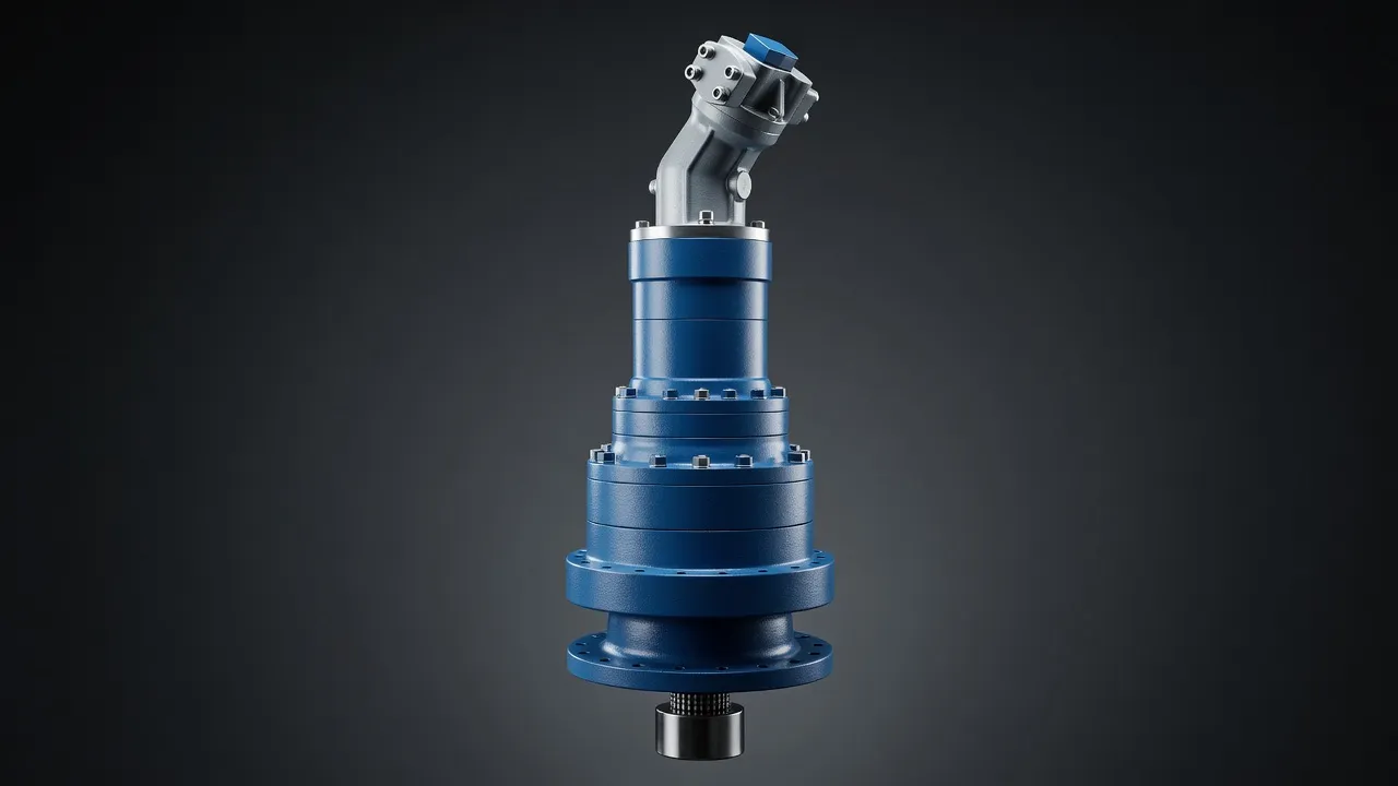
Rolling Mill Drive Architecture
A rolling mill stand consists of two or more rolls (work rolls in contact with the strip, backup rolls supporting the work rolls) driven by one or two motors through a gearbox and a pair of articulating drive spindles. The gearbox reduces the motor speed (typically 500–1 500 rpm) to the roll peripheral velocity (typically 1–10 m/s, corresponding to 30–300 rpm at the roll neck) while increasing torque by the same ratio. For a hot strip finishing mill producing 2.5 mm steel at 10 m/s entry speed, 600 mm roll diameter, and 1 200 rpm motor: required ratio = 1 200 ÷ (10 ÷ (π × 0.6) × 60) ÷ 2 = 1 200 ÷ 318 = 3.77:1 — a low ratio, achievable in a single planetary stage. For roughing mills with much lower speeds and higher torques, two or three planetary stages are required to achieve the 10:1 to 30:1 total ratio.
| Mill Type | Roll Speed | Roll Torque (per roll) | Motor Speed | Required Ratio | Planetary Stages |
|---|---|---|---|---|---|
| Hot strip roughing | 0.5–2 m/s | 2 000–8 000 kN·m | 600 rpm | 1:15–1:40 | 2–3 stage |
| Hot strip finishing | 5–15 m/s | 200–1 000 kN·m | 1 200 rpm | 1:4–1:10 | 1–2 stage |
| Cold rolling mill | 3–25 m/s | 50–500 kN·m | 1 500 rpm | 1:3–1:8 | 1 stage |
| Bar and rod mill | 5–30 m/s | 20–200 kN·m | 1 800 rpm | 1:3–1:6 | 1 stage |
| Plate mill | 0.5–3 m/s | 5 000–20 000 kN·m | 400 rpm | 1:20–1:60 | 2–3 stage |
Roll torque per roll; total drive torque = 2 × roll torque for two-roll stand.
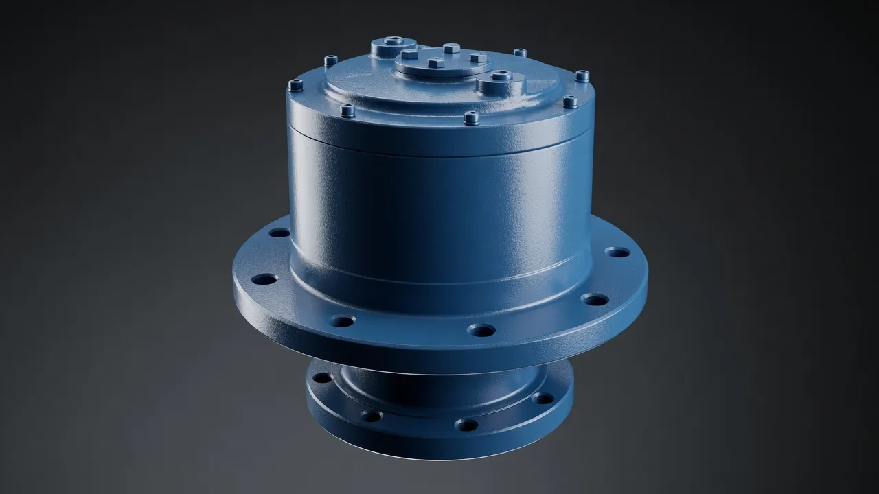
Load Sharing Across Planet Gears
The exceptional torque density of a rolling mill planetary gearbox depends on effective load sharing across all planet gears. Manufacturing tolerances in the planet pin positions, planet gear tooth geometry, and carrier arm stiffness all affect load distribution. A load distribution factor of 1.2 (one planet carries 20% more than the average) reduces the effective rated torque by 16% — the overloaded planet controls the fatigue life of the entire set. Rolling mill gearbox manufacturers achieve load distribution factors below 1.05 through floating sun gear arrangements, precision-controlled planet pin positions (typically ±0.02 mm from nominal), and helical gears whose inclined contact line spreads the load across the tooth face.
Tooth Form and Surface Treatment for Long Life
Rolling mill planetary gears operate at the maximum allowable tooth contact stress for the gear material and heat treatment — typically 1 400–1 600 MPa for 18CrNiMo7-6 case-hardened and ground gears. To achieve the required fatigue life at this stress level, the tooth root must be shot-peened to a depth of at least 0.3 mm with a compressive residual stress above 600 MPa. The tooth flanks are superfinished (Ra < 0.2 µm) to maximise the elastohydrodynamic oil film thickness at the contact zone. Manganese phosphate or DLC coating on the tooth flanks during the running-in period reduces micro-pitting risk during the first 500 hours of operation when the tooth profile is being conformally worn to its optimal contact geometry.
The EPB high-precision torque planetary series demonstrates the gear material, heat treatment, and surface finish standards that rolling mill quality demands in an industrial precision planetary format. For the largest mill drives, the EPX heavy planetary series provides the structural housing and shaft load ratings required for sustained heavy-duty mill operation.
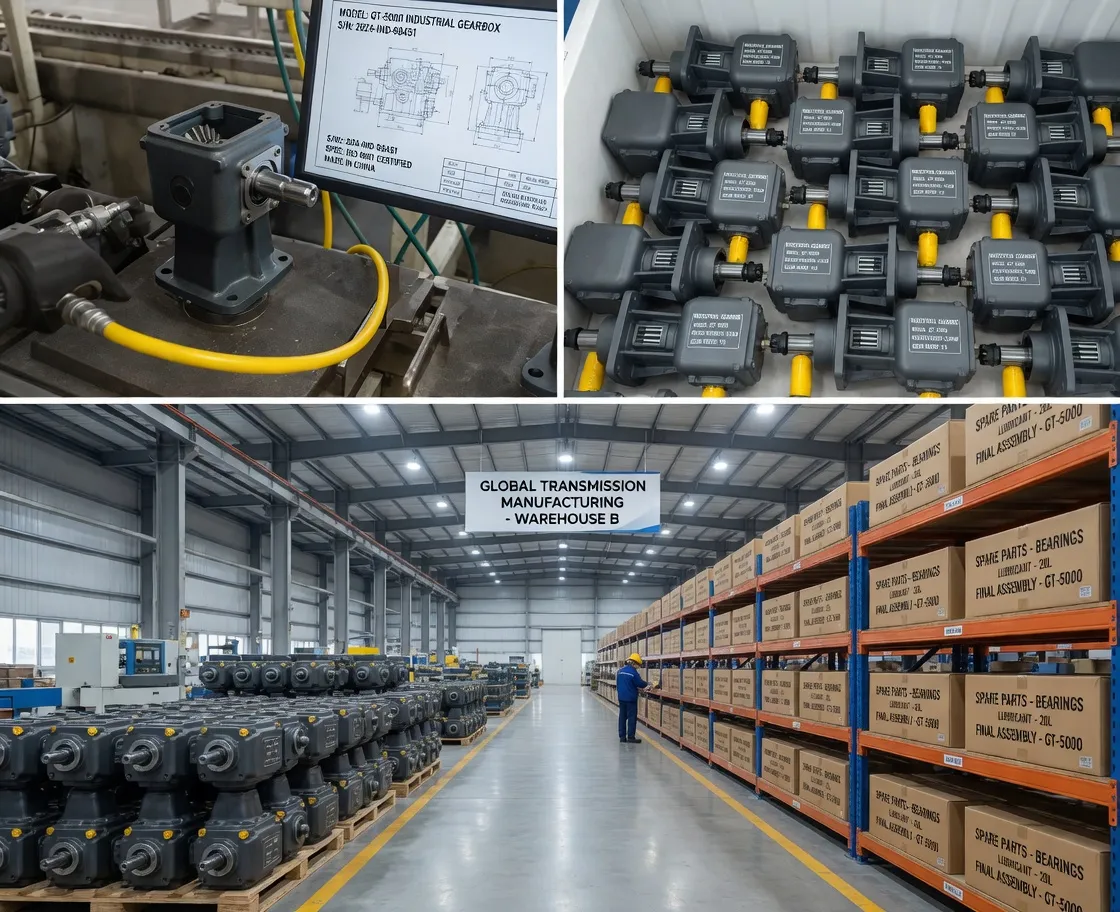
Thermal Management in Continuous Rolling Operations
A hot strip mill operates continuously — the rolling schedule runs 24 hours a day with scheduled roll changes every 2–8 hours. The drive gearboxes generate heat from gear mesh friction and bearing friction proportional to the transmitted power. For a 10 MW drive at 97% efficiency: heat generation = 10 000 × 0.03 = 300 kW per gearbox. This is substantial — a natural convection-cooled housing cannot dissipate more than 5–10 kW/m² of surface area, meaning forced oil cooling with a dedicated oil-to-water heat exchanger is mandatory. The oil circuit pressure and flow rate are monitored continuously; a low oil pressure alarm shuts down the mill before gear surface temperatures can reach the oil film breakdown point.
For comparable heavy-duty industrial drive applications where high-power continuous operation in an industrial environment is the norm, the RR528/RR577 heavy-duty worm gearbox for metallurgy provides a reference point for sealing and housing standards in metallurgical applications where a simpler gear architecture suffices at lower power levels.
Frequently Asked Questions
Speak with a Planetary Drive Specialist
Share your torque requirement, ratio, and application environment — our team at Condell Park NSW returns a sized recommendation and stock check within one business day. No obligation.