Description
Product Overview
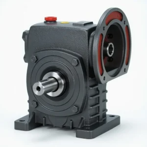
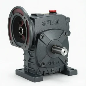
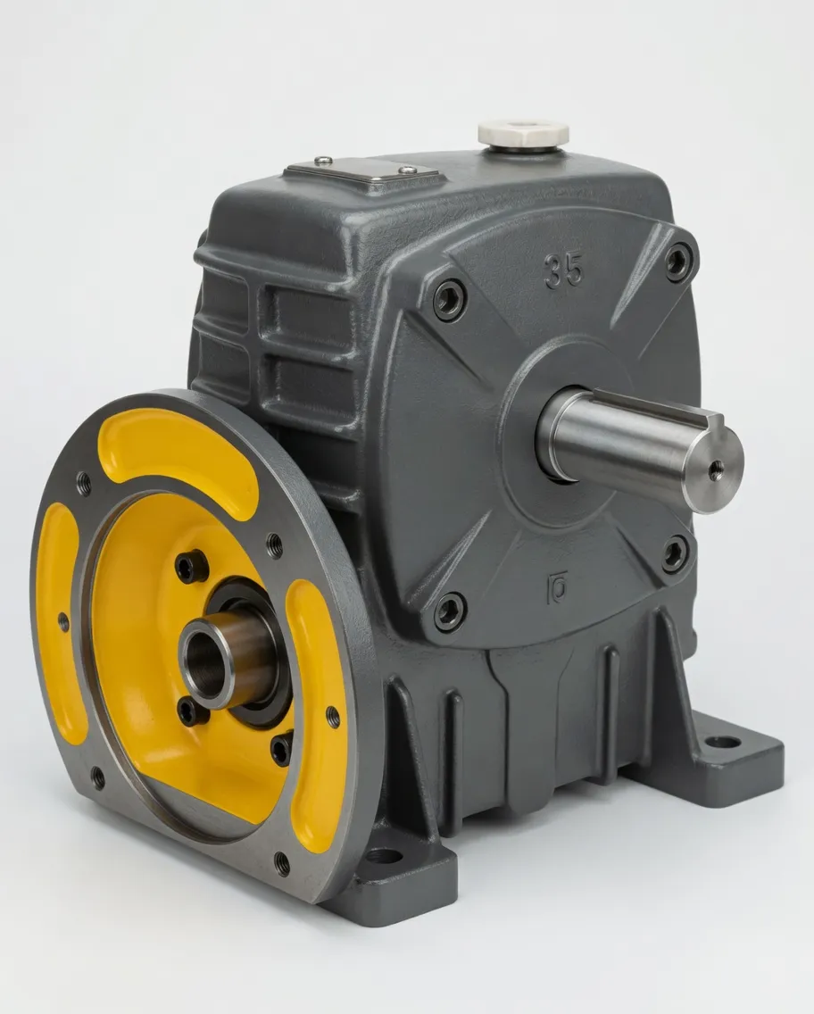
The DA Series is a single-stage worm gear reducer engineered for environments where reliable torque multiplication and compact right-angle power transmission are equally important. Built around a one-piece cast-iron housing with an integrated IEC motor flange, this unit allows the driving motor to bolt directly onto the reducer body — eliminating coupling alignment steps and shrinking the overall footprint of your drive train. With thirteen frame sizes spanning a 40–250 mm centre distance and reduction ratios from 5:1 to 60:1, the DA Series covers output torques from as low as 4 N·m on the smallest frame up to over 3,000 N·m on the WP250 housing. That breadth makes it equally at home powering a compact filling-line indexer or driving a heavy aggregate conveyor. Every unit leaves the factory pre-filled with industrial EP gear oil and sealed to prevent dust ingress, so installation is essentially bolt-on-and-run. Six standard shaft orientations (A through F) let engineers adapt the same core gearbox to vertical, horizontal, or inclined layouts without sourcing a separate product line.
Technical Specifications
The table below summarises the key performance figures for every DA Series frame at 1,500 r/min input speed. Matched motor power ratings follow the A02 / Y-series IEC standard, and torque values reflect continuous-duty capacity under normal ambient conditions (10–25 °C). For installations above 30 °C or subject to cyclic shock loading, apply the published thermal and working-condition correction factors. All dimensional data conforms to GB/T standards and is interchangeable with equivalent WP-type cast-iron speed reducer gearbox platforms available in the Australian market.
| Frame Size (mm) | Motor Power (kW) | Ratio Range | Output Torque at 10:1 (N·m) | Max Output Torque (N·m) |
|---|---|---|---|---|
| WP40 | 0.12 | 5:1 – 60:1 | 6 | 20 |
| WP60 | 0.37 | 5:1 – 60:1 | 19 | 73 |
| WP80 | 0.75 – 1.5 | 5:1 – 60:1 | 77 | 248 |
| WP100 | 1.5 | 5:1 – 60:1 | 80 | 344 |
| WP120 | 2.2 – 3 | 5:1 – 60:1 | 151 | 521 |
| WP135 | 3 – 4 | 5:1 – 60:1 | 219 | 690 |
| WP175 | 5.5 – 7.5 | 5:1 – 60:1 | 415 | 1,450 |
| WP200 | 11 | 10:1 – 60:1 | 623 | 2,856 |
| WP250 | 11 – 15 | 10:1 – 60:1 | 850 | 3,025 |
Transmission Efficiency by Ratio
Worm gear efficiency varies inversely with reduction ratio owing to the sliding contact between worm threads and wheel teeth. The values below assume properly run-in gear surfaces with recommended EP220–EP320 lubricant at standard temperature. Higher ratios produce more heat per revolution and benefit from synthetic oil or forced-air cooling in continuous-duty cycles above eight hours.
| Ratio | Efficiency Range |
|---|---|
| 10:1 | 76 – 90 % |
| 15:1 | 75 – 86 % |
| 20:1 | 74 – 84 % |
| 30:1 | 68 – 70 % |
| 40:1 | 65 – 75 % |
| 60:1 | 60 – 70 % |
Design Features and Engineering Advantages
One-Piece Cast-Iron Housing
The DA Series uses a monolithic (non-split) grey cast-iron housing that wraps the worm shaft and worm wheel in a single rigid enclosure. Compared with split-case designs, this construction eliminates the parting-line gasket — a common source of oil leaks — and provides a stiffer bearing span for the output shaft. Surface machining on the foot pad and the IEC motor flange face is carried out in one setup, guaranteeing coaxial alignment between the motor input bore and the worm centreline without shimming.
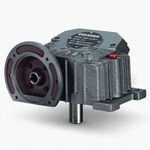
Integrated IEC Motor Flange
A machined B5/B14-pattern flange on the input side accepts A02- or Y-series motors directly. The splined input bore and keyway are finished to h6 tolerance, which means the motor shaft slides in without excessive force yet holds concentricity within acceptable limits. This direct-mount approach removes the belt, coupling, or chain that a foot-mounted arrangement would otherwise need, cutting both radial space and the number of wear parts in the drivetrain. For installations where the motor mass is significant, an optional TV-type motor support bracket can be fitted to transfer weight away from the worm-shaft bearing.
Self-Locking Capability
At ratios above roughly 30:1, the helix angle of the worm falls below the static friction angle of the bronze-on-steel mesh, which means the output shaft cannot back-drive the worm under gravity or external load. This inherent self-locking worm gearbox behaviour is valuable in lifting hoists, gate actuators, and tilting tables where the load must stay in position when the motor stops — no additional brake is required.
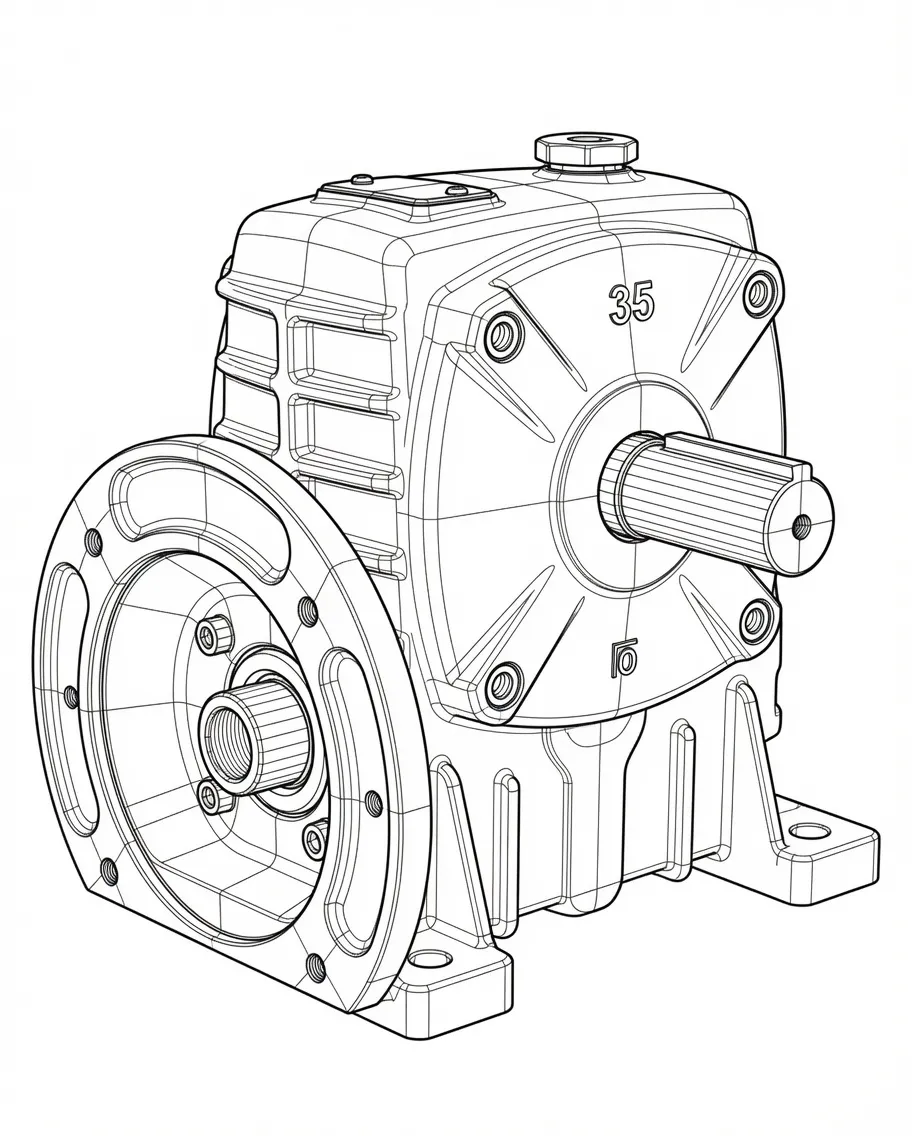
Dimensional outline showing shaft orientation A through F
Mounting Configurations and Shaft Orientations
One of the practical strengths of the DA Series is that a single gearbox casting supports six distinct shaft positions labelled A through F. Position A places the input (motor) shaft below the output axis — the most common arrangement for floor-level conveyor drives. Positions C and D rotate the flange to face outward, useful on vertical panel-mounted packaging machines. Positions E and F point the motor upward or downward to accommodate overhead or pit-mounted drives. Because the housing, gear set, and bearings are identical across all six orientations, spares inventory remains minimal. The foot pads are machined on two perpendicular planes so the same unit can be bolted either horizontally or vertically without modification.
Industry Applications
Food, Beverage and Packaging
DA Series reducers in the WP60 to WP100 range are widely fitted to rotary filling machines, capping heads, and label applicators where precise, low-speed indexing matters. The right angle worm gearbox layout lets the motor sit parallel to the machine frame while the output shaft drives a cam or turntable perpendicular to it — a geometry that suits the tight spaces inside packaging cells on lines from brands such as Krones and Sidel. At 20:1 or 30:1, these units self-lock reliably, holding the turret in position during the dwell phase without an auxiliary brake.
Material Handling and Conveyors
Belt conveyors, roller tables, and screw feeders in mining, aggregate, and grain-handling facilities rely on the larger WP135–WP250 frames for continuous torque delivery at low output speeds. A WP175 at 40:1 produces just over 1,000 N·m — enough to start a loaded belt from rest without a soft-starter on the motor, thanks to the worm gear’s inherent torque-smoothing action. The cast-iron housing withstands vibration typical of crushing and screening environments, and the sealed construction prevents ore dust from contaminating the lubricant.
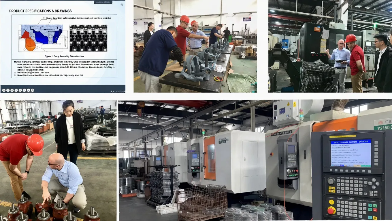
CNC gear-cutting and housing machining at our production facility
Lubrication and Maintenance Guidelines
Correct lubricant selection is the single most impactful maintenance decision for any worm gear unit because the bronze-on-steel sliding contact depends on an oil film to limit friction and carry away heat. For ambient temperatures between −30 °C and 40 °C, use an ISO VG 220–320 mineral gear oil — Shell Omala S2 G 220 or Mobil DTE Oil BB are well-proven choices. In warmer environments (40–65 °C), step up to VG 320–460 or consider a PAO synthetic for extended drain intervals and lower operating temperature. Fill the housing to the sight-glass marker; both over-filling and under-filling cause problems.
Drain the factory oil after the first 100 hours of operation and replace it with fresh lubricant. After that initial change, follow a 2,500-hour service cycle or once per year, whichever comes first. During each oil change, inspect the magnetic drain plug for metal particles. A light coating of fine bronze dust is normal during run-in; coarse steel chips indicate bearing or tooth damage that warrants further investigation.
How to Order Your DA Series Reducer
Getting the right unit is straightforward. Follow the steps below or contact us directly with your motor and load parameters — our engineers will size the reducer for you at no charge.
Define Your Load
Determine the required output torque (N·m), output speed (r/min), and duty cycle. Note any shock-load or frequent-start conditions.
Pick the Ratio
Divide the motor speed (typically 1,500 r/min) by the desired output speed. Match the result to the nearest standard ratio between 5:1 and 60:1.
Choose the Frame
Cross-reference the torque table to find the smallest frame whose rated torque at your ratio exceeds the required torque after applying correction factors.
Specify Orientation
Decide on shaft position A–F to suit your installation layout. Specify solid or hollow output shaft if the KA variant is needed.
Get a Quote
Send us the model string (e.g. WPDA-120-1/30-A) together with your motor specs. We respond within 24 hours with pricing and lead time.
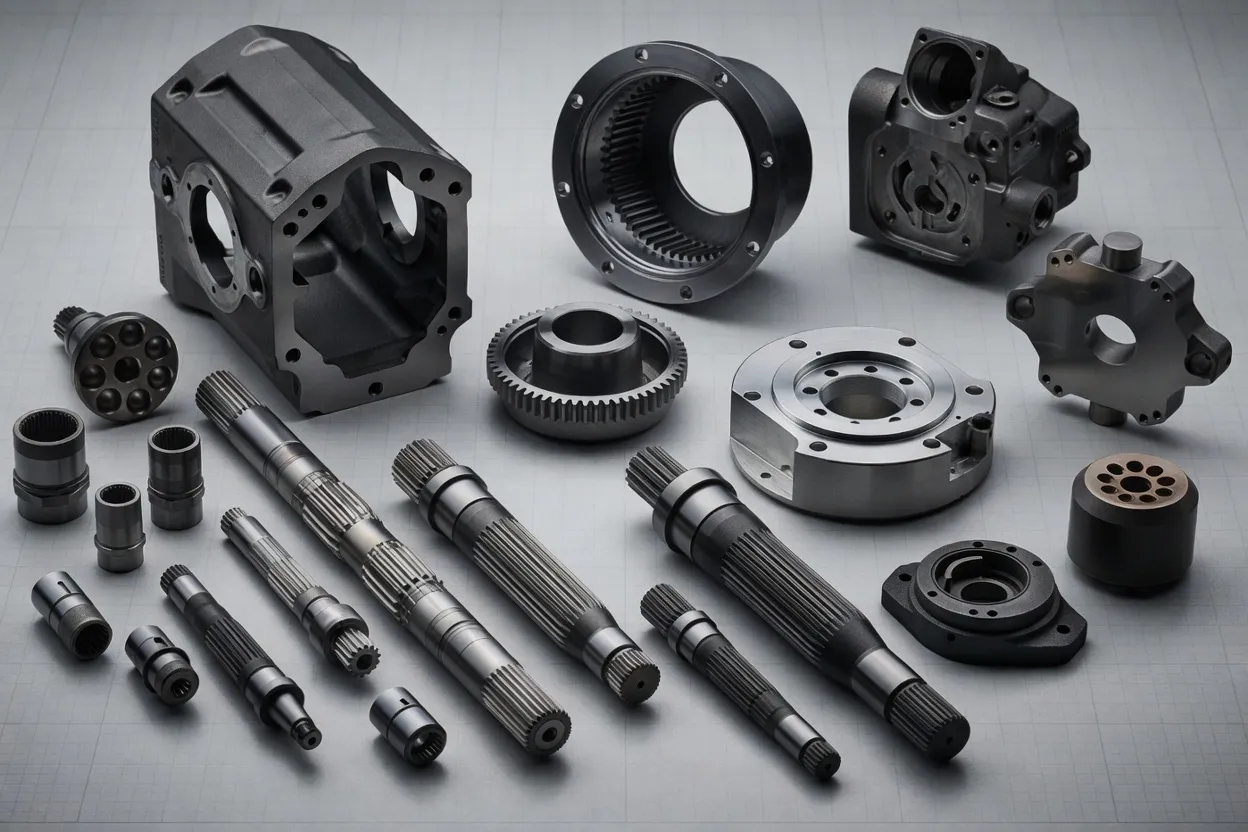
Precision-ground worm shaft and tin-bronze worm wheel
Why Choose Ever-Power Transmission Australia
Ever-Power Transmission Australia Pty Ltd maintains a local warehouse in Condell Park, NSW, stocking the most popular DA Series frame sizes for same-week dispatch across Australia and New Zealand. Every reducer is built under an ISO 9001-certified quality system and dimensionally verified before shipment. Our Sydney team understands Australian standards, supply-chain timelines, and freight logistics. Whether you need a single WP40 for a prototype or a bulk order of WP200 units for a mine-site conveyor rollout, we provide consistent pricing, traceable documentation, and after-sales support including replacement worm-wheel sets and seal kits. We also supply complementary lines such as NMRV aluminium-alloy worm gearboxes for lighter-duty applications where corrosion resistance or weight savings matter.